Basic Operation
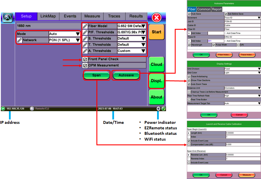
The FL150 will power up to the FaultScout Setup screen. Default setup assumes user wants to perform Auto (single pulse) with V-Scout available (multi-pulse). Network default is ONT to Splitter test on a PON drop fiber. Splitter to ONT, PON (1SPL) and P2P also available. Other test parameter and factory default settings are:
-
Fiber Model/Type: G.652 SM
-
Pass/Fail Thresholds: G.697/G.98x PON
-
Splitter Thresholds: Default
-
Tap Thresholds: Default
-
Analysis Thresholds: Default
Select other Parameter profiles or create customer profiles using the pencil icon to edit.
Other Parameter default settings are:
-
Front Panel Check: warns user that signal level is low or reflection level is excessive
-
OPM Measurement: measure incoming signals using in-line dual PON 1490/1577 prior to testing PON network.
-
SPAN: Used to setup launch or receive fibers, default = NONE; Initial event loss is excluded in Total Link Loss
-
Show Section Loss: Do not show dB/km between events in Event table view
-
Auto Zoom: Expand link in viewing window to show start to end.
Setup and additional tools such as FiberScope can be accessed by tapping the applicable System button and selecting the Tools options.
For more details about System Settings, see the V150 Common Functions Manual on www.veexinc.com.
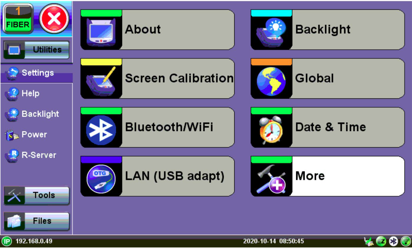
System Setting – Utilities/Tools/Files Menu
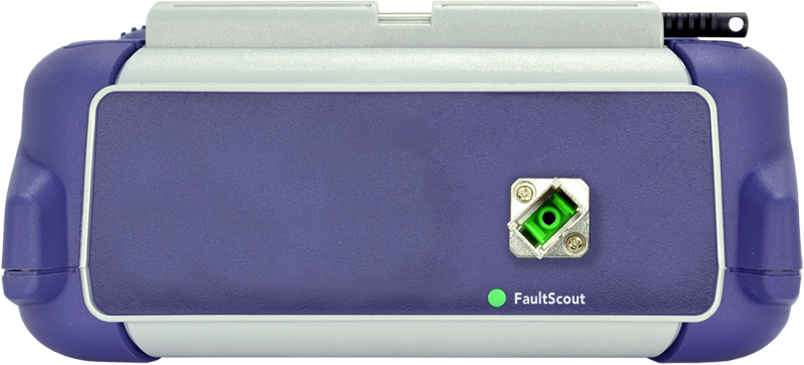
Test Ports and Interfaces
FaultScout testing: The optical fiber under test is connected to the FaultScout port on the top panel (a SC/APC connector). Closing the dust cap when the meter is not in use will minimize dust ingress or air pollution contamination.
![]() Optical Connections
Optical Connections
Connector contamination/damage is the main reason test sets have to be returned for repair. Daily inspection and cleaning of the FL150 test port is recommended. Always clean patchcord connectors prior to connecting to the fiber under test. Dust, dirt and pollution severely impact optical performance. Inspect/Clean connectors when excessive Loss or Reflectance/ORL is observed in measurements. In the Setup, activating Front Panel Check can alert you to abnormal connection to meter.
Front Panel Layout
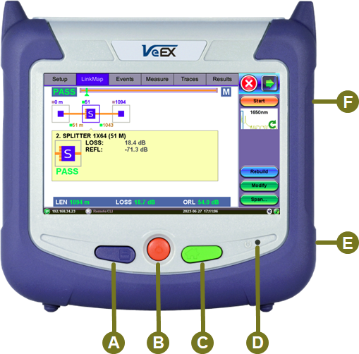
A+B Clean Software Update Installation
-
Starts software update process, wipes internal storage restore factory setting
B+C Software Update Installation
-
Keeps test results, test profiles and user setting
A+C Invokes the Screen Calibration Procedure
-
Provides touch screen calibration if it can’t be accessed by GUI
A+F Screen Capture function
F Slider Button provides Page Scroll function
Others:
D Power ON and Battery Charge Indication LED
E micro-B USB interface (includes USB-A OTG adapter cable)
LED Indicators
Power/Charge LED: indicates battery charging is in progress. LED turns off when battery is fully charged.
![]() The device is powered from the built-in Li-Ion battery and can be operated with the AC/ DC adaptor plugged in.
The device is powered from the built-in Li-Ion battery and can be operated with the AC/ DC adaptor plugged in.
Keypad

-
Save: Saves the test results.
-
Power: Press for 2 seconds to turn the test set ON or OFF (prevents accidental ON/OFF).
-
Home: Resets user interface to Main menu.
-
Right side + Save: Saves the screen (bmp).
-
Right side + Home: Hibernates device.
-
Power + Home: Updates software.
Quick Start Guide
FaultScout
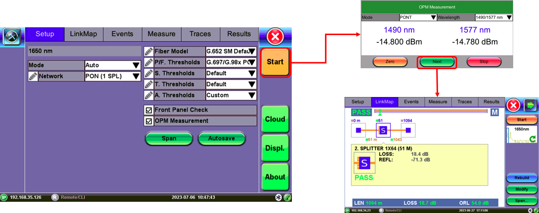
The FL150 test set can be used to test PON or P2P fiber. For PON, set up to view PON-T downstream signals prior to starting Fault Location.
The steps to running the test set are:
-
Power on the test unit to display the FaultScout screen.
-
Select Setup and then select Auto ONT to Splitter, Splitter to ONT, PON (SPL1) or P2P for single pulse tests. Use V-Scout mode for multi-pulse tests.
-
Tap the pencil icon to edit test profiles. Check Front Panel Check or OPM Measurement, if desired.
-
To begin test, press START, close dust cap and tap Zero in the OPM window.
-
Inspect and Clean FaultScout test port and patchcord connectors before connecting test fiber.
-
Tap Next if optical signals are acceptable to continue with checking the fiber. The results are displayed in the LinkMap. Span Length, Event Type/Loss, and RL. Pass/Fail indication depends on P/F Thres setting profile entered in the Setup Menu. Use Events or Measure view traces.
7. Tap an event icon to view more details.
Screen Navigation
![]() Touch Screen Navigation
Touch Screen Navigation
The unit is equipped with a state of art, full color, LCD TFT touch screen. When used properly, the screen is designed to give years of reliable and precise operation. Always use the stylus supplied with the unit to operate the touch screen. Never use any sharp object such as a ballpoint pen, screwdriver, or similar item as this will damage the screen and void the warranty. The touchscreen can be recalibrated when needed.
![]() Each test mode has their own Setup which may look different.
Each test mode has their own Setup which may look different.
Inserting the Fiber
Match connector alignment key to test port slot before attempting to insert connector into the test port; avoid rubbing the fiber against the external part of the port or any other surface.
Push the connector in and you will hear a click. Make sure the optical connector is inserted fully to guarantee good contact.
Preventing Inaccurate Readings
To achieve maximum power and prevent false readings, always clean test port and the optical fiber connector before inserting it into the test port and bulkhead connectors.
Confirm the correct fiber connector polish type is the same as the test port, before inserting any connector into the test port. Mismatched connector polish may damage the optical end faces of the test set or the Connector Saver plug.
![]() If the optical fiber is not aligned properly and/or completely connected, it will cause serious loss and reflection. In addition, contaminated or damaged connectors can impact performance and result in false event detection.
If the optical fiber is not aligned properly and/or completely connected, it will cause serious loss and reflection. In addition, contaminated or damaged connectors can impact performance and result in false event detection.