Thresholds
![]() Microbends require two different wavelengths. When setting the thresholds, enter the loss difference between the two wavelengths. The trace will report when the loss exceeds the macrobend threshold and be displayed in the LinkMap.
Microbends require two different wavelengths. When setting the thresholds, enter the loss difference between the two wavelengths. The trace will report when the loss exceeds the macrobend threshold and be displayed in the LinkMap.
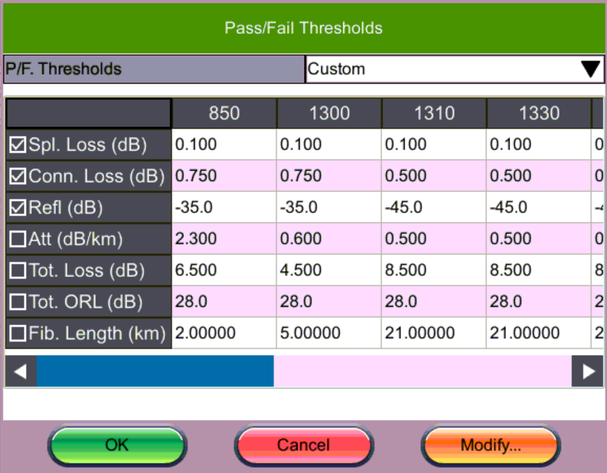
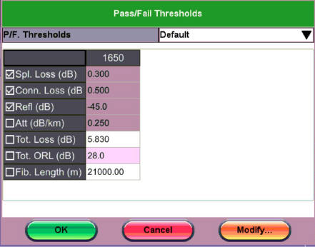
Select factory default settings (Default) or to enter threshold values that match test requirements, select Custom. Events that fail to meet the Pass/Threshold will be flagged and highlighted as red in the event table.
Pass/Fail Thresholds
Events exceeding the Pass/Fail Thresholds are highlighted in Red in the Event table. Different Pass/Fail Thresholds values can be set for each test wavelength.
Event Loss (splice, connectors, mux) and Reflectance threshold settings determine if a detected anomaly should be reported.
Pass/Fail Thresholds
Each column heading displays the wavelength to which the Pass/Fail Thresholds apply.
- Splice loss (dB) - Non-Reflective Event Loss. The range for this parameter is 0.001 dB to 9.99 dB in 0.001dB increments. For mated APC connectors, if there is no reflection, the loss reports as Splice.
- Connector Loss (dB) - Reflective Event Loss (connectors and mechanical splices). The range for this parameter is 0.001 dB to 9.99 dB in 0.001 dB increments.
- Reflectance (dB) - Events in the Event table exceeding the set Reflectance value. The range for this parameter is -50.0 dB to -10.0 dB in 0.1 dB increments.
- Attenuation (dB/km) - Average Fiber Section Loss in dB/km that exceeds the set value.
- Total Loss (dB) - Total fiber loss in dB for Fiber-Under-Test (FUT) that exceeds the set value.
- Total ORL (dB) - Total Optical Return Loss in dB for Fiber-Under-Test (FUT) that exceeds the set value.
- Fiber Length (km, miles) - Total fiber length that exceeds set value.
To modify values, select the P/F threshold from the drop-down list. Then, tap Modify to Fill, Add, Rename, or Remove values.
MUX Thresholds
Analysis Thresholds