Basic Operation
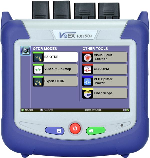
To power on the FX150+ test set, press ![]() for approximately two seconds, until the test set beeps once. See Hard Buttons and Interfaces for more information on the test set's buttons and interface.
for approximately two seconds, until the test set beeps once. See Hard Buttons and Interfaces for more information on the test set's buttons and interface.
LEDs
Power LED: A single LED indicates the power state of the unit
-
The LED is off when the unit is powered off.
-
The LED is green when the unit is powered on.
-
The LED is orange when the unit is connected to the AC Mains and powered off (charging).
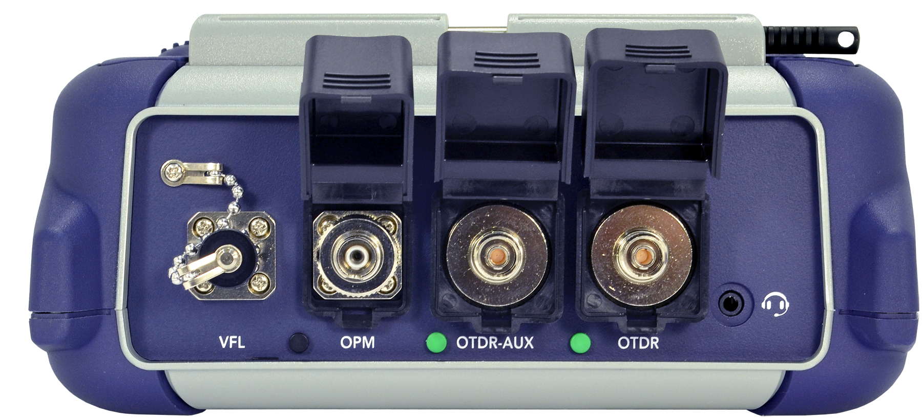
Test Ports and Interfaces
OTDR: The optical fiber under test is connected to either the OTDR or AUX (Filtered SM or MM) port on the top panel. The type of the optical fiber connector must correspond to the OTDR connector or adaptor type, including the connector polish.
Optical Power Meter (OPM): The optical fiber is connected to the non-contact OPM port on the top panel. Depending on fiber connector type, use interchangeable adaptors.
Visual Fault Locator (VFL): (optional) The optical fiber is connected to the VFL port on the top panel. The VFL interface is fitted with universal 2.5mm sleeve accepting all 2.5 mm connector ferrules. A 2.5mm to 1.25mm converter is available for the LC type connector.
Field-Replaceable Optical Ferrule System
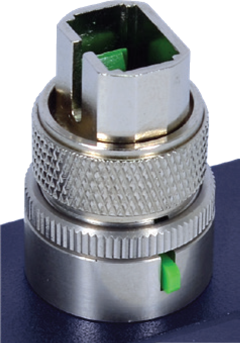
The innovative, patent pending field-replaceable optical ferrule system![]() adds an extra layer of protection to the internal end-face of calibrated optical test ports, preventing contamination and accidental damage.
adds an extra layer of protection to the internal end-face of calibrated optical test ports, preventing contamination and accidental damage.
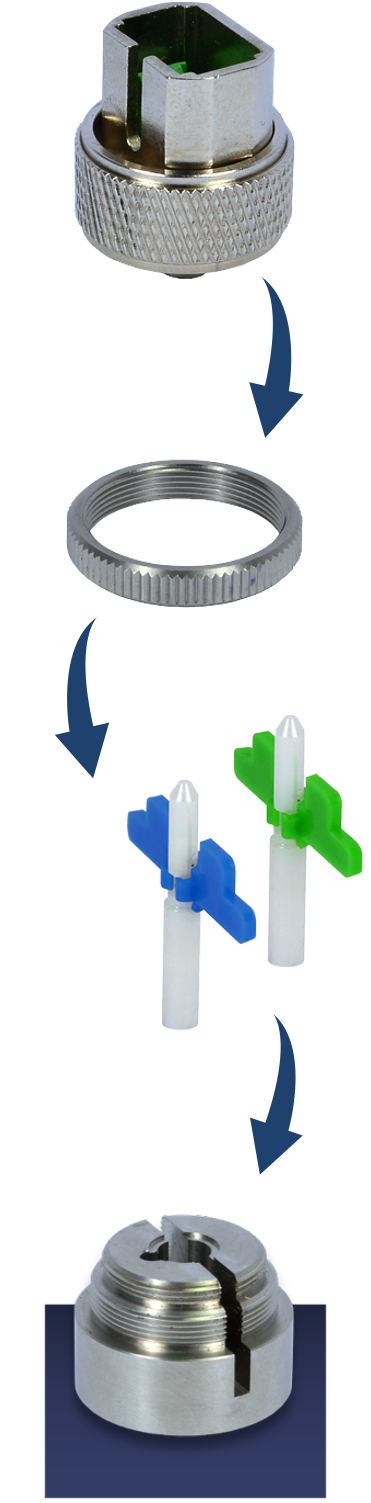
Quickly replace the ferrule![]() without the need for any tool while maintaining the integrity of the instrument’s factory calibration. This novel approach eliminates the downtime, logistical hurdles and high cost associated with sending test sets to a service center for repair and recalibration.
without the need for any tool while maintaining the integrity of the instrument’s factory calibration. This novel approach eliminates the downtime, logistical hurdles and high cost associated with sending test sets to a service center for repair and recalibration.
All components in the system are reusable, with the exception of the small replaceable ferrule, helping to reduce environmental waste.
Universal Adapter
The universal connector adapter allows users to change the optical connector type conveniently whenever needed. Available in FC, SC, ST and LC.
Locking Ring
To secure the replaceable ferrule at its optimum location for the best performance.
Replaceable Ferrule with APC or UPC End-face
The self-aligned field-replaceable ferrule can be changed out in seconds. Users can select between APC or UPC end-face, ensuring compatibility with any test application requirement.
Optical Connector Protector Base
The panel mount protector base is made from high-grade stainless steel using a precision CNC process. This achieves proper alignment of the replaceable ferrule, minimizing insertion loss.
![]() Optical Connections
Optical Connections
Connector contamination/damage is the main reason test sets have to be returned for repair. Daily inspection and cleaning of test ports is recommended. Always clean test ports and patchcord connectors prior to connecting to the fiber under test. Dust, dirt, and pollution severely impact optical performance. Inspect/Clean connectors when excessive Loss or Reflectance/ORL is observed in measurements. In the Setup tab, activating Front Panel Check can alert you to abnormal connection to meter.
For more information on fiber handling procedures and tip cleaning, see "CLIC" - Clean to Maintain Optical Connector Quality.
Standard OTDR or PON optimized OTDR
-
Supports up to 4 wavelengths max MM or SM
-
MM: 850, 1300 nm
-
SM: 1310, 1490, 1550, 1625 and 1650 nm
-
-
Dynamic range up to 46 dB
-
Testing long Point-Point fiber links up to 200 km (124 miles)
-
Testing single or cascaded PON up to 1:256 splitter ratios using balanced, unbalanced, or taps
-
-
Optimized dead zones (DZ) for FTTx/PON applications
-
Event 0.8 m, Attenuation 3.5 m typical
-
PON ≤16.5m (13 dB loss, 25 ns PW, non-reflective splitter)
-
-
Filtered OTDR port for in-service testing at 1625 or 1650 nm
-
Live fiber detection with embedded power meter
-
Telcordia SR-4731.sor file format
-
Generate and save results in sor, png or pdf formats
-
Auto mode - setup, events detection, and trace diagnostics
-
V-Scout option – displays intuitive icons derived from multiple test acquisitions
-
PON OTDR for different PON link configurations - balanced, unbalanced, and/or taps
-
Markers for distance, attenuation, reflectance and splice loss measurements
-
Fixed or Universal interface option with interchangeable optical adapters (SC, ST, FC) for OTDR port
-
Power meter, light source, fiber inspection probe, and VFL
-
Remote measurement using EZ Remote, VNC, or built-in web based software