Thresholds
![]() Microbends require two different wavelengths. When setting the thresholds, enter the loss difference between the two wavelengths. The trace will report when the loss exceeds the macrobend threshold and be displayed in the LinkMap.
Microbends require two different wavelengths. When setting the thresholds, enter the loss difference between the two wavelengths. The trace will report when the loss exceeds the macrobend threshold and be displayed in the LinkMap.
Select the Thresholds drop-down arrow and select factory default settings (Default) or the profile with threshold values that match test requirements. Choose Custom to create a new profile with custom settings. Events will be placed into the table only if the threshold is met/exceeded. Events that fail to meet the pass/threshold will be flagged and highlighted as red in the event table.
Pass/Fail Thresholds
Events exceeding the Pass/Fail Thresholds are highlighted in Red in the Event table. Different Pass/Fail Thresholds values can be set for each test wavelength.
Event Loss (splice, connectors, mux) and Reflectance threshold settings determine if a detected anomaly should be reported
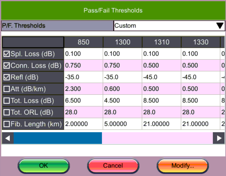
OTDR Setup: Pass/Fail Thresholds
Each column heading displays the wavelength to which the Pass/Fail Thresholds apply.
- Splice loss (dB) - Non-Reflective Event Loss. The range for this parameter is 0.001 dB to 9.99 dB in 0.001dB increments. For mated APC connectors, if there is no reflection, the loss reports as Splice.
- Connector Loss (dB) - Reflective Event Loss (connectors and mechanical splices). The range for this parameter is 0.001 dB to 9.99 dB in 0.001 dB increments.
- Reflectance (dB) - Events in the Event table exceeding the set Reflectance value. The range for this parameter is -50.0 dB to -10.0 dB in 0.1 dB increments.
- Attenuation (dB/km) - Average Fiber Section Loss in dB/km that exceeds the set value.
- Total Loss (dB) - Total fiber loss in dB for Fiber-Under-Test (FUT) that exceeds the set value.
- Total ORL (dB) - Total Optical Return Loss in dB for Fiber-Under-Test (FUT) that exceeds the set value.
- Fiber Length (km, miles) - Total fiber length that exceeds set value.
To modify values, select the P/F threshold from the drop-down list. Then, tap Save As and enter a new name for the thresholds profile.
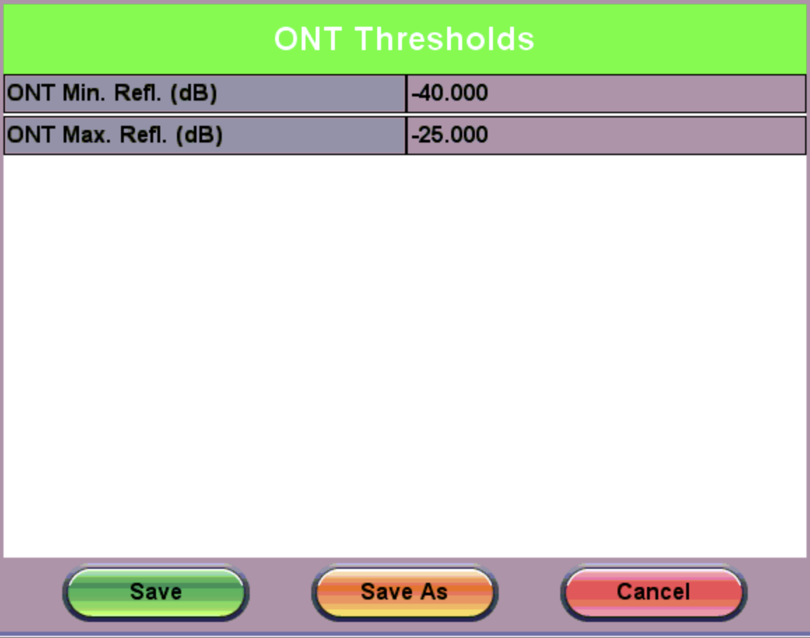
ONT Thresholds
ONT Thresholds define the reflectance threshold value for the ONT side. The default ONT Thresholds are locked from editing.
ONT Thresholds
To define new ONT Thresholds:
-
Tap the pencil icon
 to the left of the ONT Thresholds field showing Default in the drop-down.
 -
Tap Save As and enter a new custom name.
-
Then, select the new custom thresholds from the drop-down and tap pencil icon
to the left of the ONT Thresholds field to access the ONT Thresholds screen. -
Tap the field to assign new values for the thresholds and tap Save.
Splitter Thresholds
Splitter Thresholds define the splitter loss values to be applied when building the LinkMap.
Click the pencil icon ![]() to the left of the S. Thresholds field to access the Splitter Thresholds screen and enter custom threshold settings.
to the left of the S. Thresholds field to access the Splitter Thresholds screen and enter custom threshold settings.
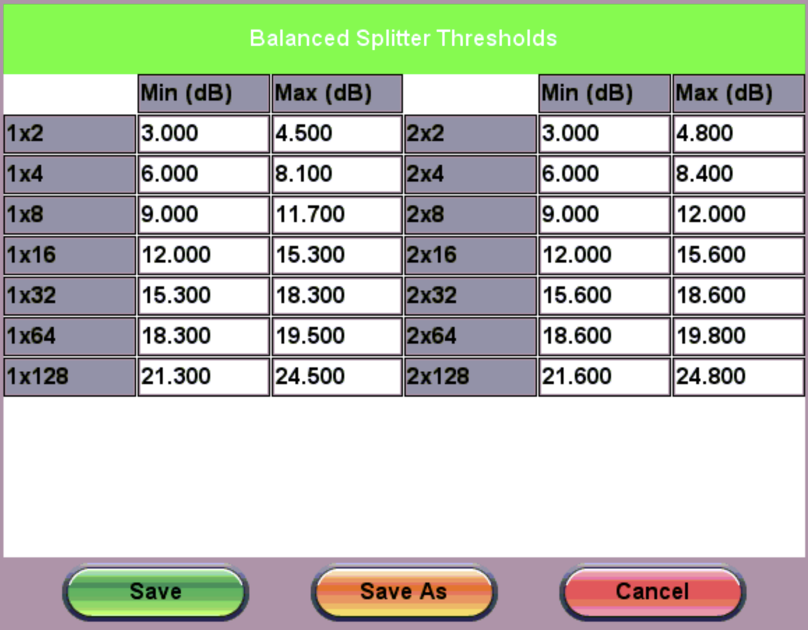
Splitter Thresholds
Tap Splitter Thresholds
The T. Thresholds field define loss values at the tap. Select the pencil icon ![]() to the left of the T. Thresholds field to access the Tap Splitter Thresholds screen and enter custom threshold loss values. The Term Tap field appears to balance remainder.
to the left of the T. Thresholds field to access the Tap Splitter Thresholds screen and enter custom threshold loss values. The Term Tap field appears to balance remainder.
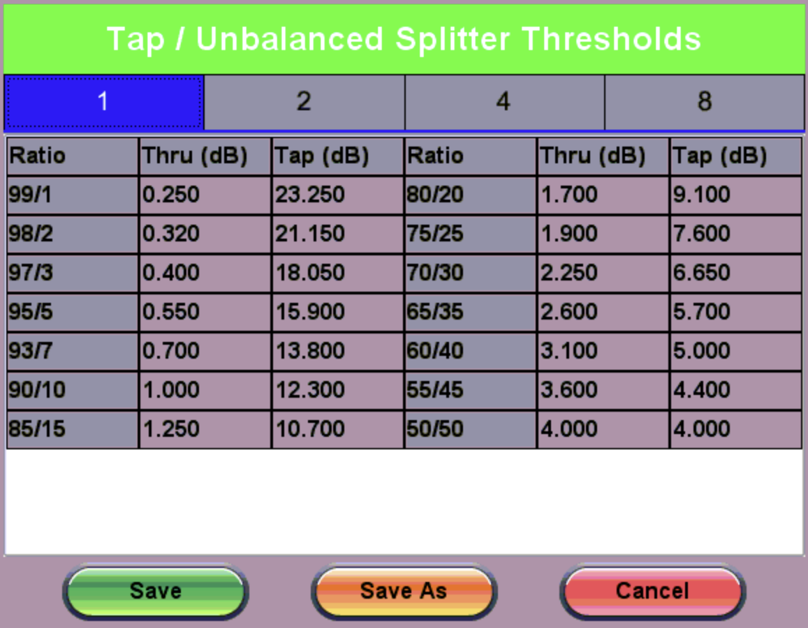
Tap Splitter Thresholds
Analysis Thresholds
Tap the pencil icon ![]() to the left of the A. Thresholds field to access the AnalysisThresholds screen and enter custom threshold settings.
to the left of the A. Thresholds field to access the AnalysisThresholds screen and enter custom threshold settings.
The Fiber End default value is 5dB.
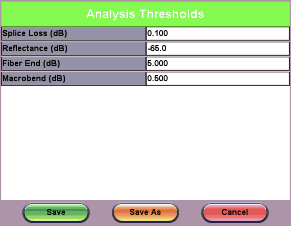
Analysis Thresholds
Events that exceed the Analysis Threshold settings are reported in the Event table. These parameters include:
- Splice Loss (dB) - The setting range for this parameter is 0.01 dB to 9.99 dB in 0.01 dB increments. The default value is 0.020dB.
- Reflectance (dB) - Defines the lowest Reflectance value that will be reported by the analysis. The setting range for this parameter is -70.0 dB to -20.0 dB in 0.1 dB increments. The default value is-65.0dB.
- Fiber End (dB) - Defines the value which will be reported in the Events analysis. The setting range for this parameter is 1 dB to 99 dB in 1 dB increments. The default value is set to 20dB but for non-PON spans, a 3dB value is recommended.
- Macrobend (dB) - Defines the detection value with a default value 0.200dB.
 A non-reflective event will be reported as a macrobend if its loss at a longer wavelength exceeds its loss at a shorter wavelength. Macrobend detection requires at least two singlemode wavelengths being tested - 1310 nm and another either at 1550 nm or 1625 nm. The range for this parameter is 0.3 dB to 2 dB in 0.1 dB increments. The default value is 0.2dB.