Capture Images (View)
The Capture tab is the main user interface for the connector end face inspection and analysis. It presents a real-time view of the connector’s end face allowing for alignment and focus. Page 1 of the capture screen displays a live image of the connector face and features analysis and freeze tools.
The fiber end face image will normally display near the middle of viewing window area. The exception will be when inspecting bulkhead/couplers of APC connectors or using A6 type tips. The end face image will appear off-center. AutoFocus and Shake OFF setting is recommended when inspecting couplers. Gently adjust centering while manually focusing the image and image will freeze as soon as focus is achieved.
For the DI-3000, press the autofocus (red target) button when the image is out of focus to enable the device's automated focusing operation. With a steady hand, the end face will be promptly autofocused and ready for capture.
![]() Initially, there is no screen shown until Resume is pressed.
Initially, there is no screen shown until Resume is pressed.
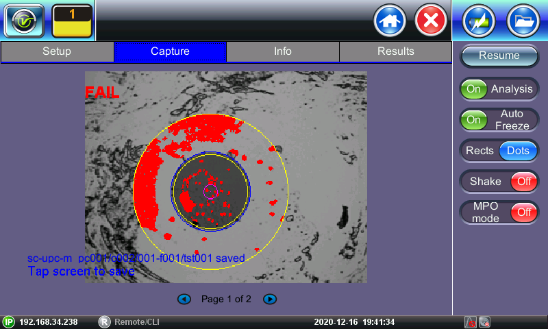
Real time video of the connector face. Red contours indicate scratches and defects.
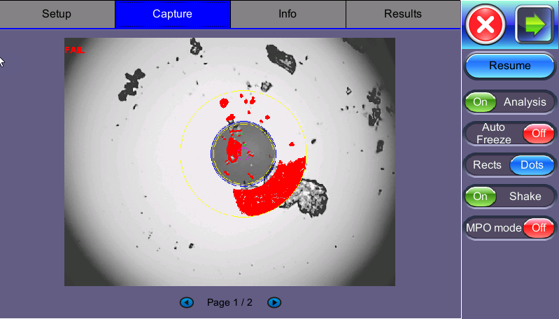
Fiber Scope Capture - Dots vs Rectangles
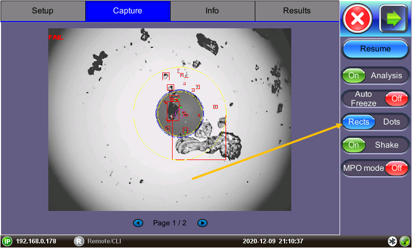
Rects function highlighting overlay
The radio buttons on the right panel do not indicate the current state or setting, they indicate the action that would take place if pressed. For example, if “Analysis OFF” is tapped, the analysis function is turned OFF and the button displays “Analysis ON”.
-
Resume / Freeze: Stops the video capture from the fiberscope. If the optional Auto Freeze feature is enabled, the test set will automatically freeze the image when it comes into focus. Once the image is frozen, tap the image to save it.
-
Analysis On / OFF: Turn ON/OFF the automatic Pass/Fail threshold defined by IEC 61300-3-35.
-
Auto Freeze: Turn ON/OFF the ability to freeze the video automatically, when in Focus. The default is set to OFF. To see the image after it freezes, tap Resume.
![]() Auto Freeze may be useful when scoping certain angled polish fibers.
Auto Freeze may be useful when scoping certain angled polish fibers.
-
Rectangles / Dots: Dots draw a red contour around scratches and defects. Rectangles highlight scratches and defects without obstructing the view. The selection between dots or rectangles does not affect the area calculation or the Pass/Fail results. Dots are set as default.
-
Shake: Turn ON or OFF the ability to Auto Freeze or Analyze when probe image is unsteady, such as when inspecting a female connector or bulkhead. It minimizes significant vibrations and unsteadiness generated from the fiberscope being held. Typically, this function is not always needed with the use of image focusing.
When inspecting bulkhead couplers or MUX/transceivers set Shake to OFF.
-
MPO mode: Turn ON when inspecting ribbon fibers (MPO/MPT connectors). Create a New Group for each MPO ribbon and Capture Fiber to save an image for each strand.
![]() When inspecting MPO/MPT connectors, it is recommended to set Auto Freeze and Shake to OFF.
When inspecting MPO/MPT connectors, it is recommended to set Auto Freeze and Shake to OFF.
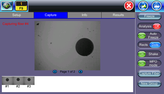
Fiber Scope MPO mode
To save the image on the screen, tap the screen after freezing.
After saving, go to Results or > Utilities > FilesFiles to view the report and export to PDF or USB.
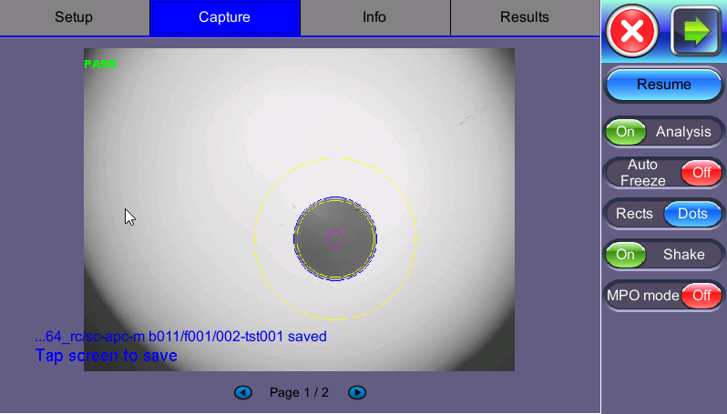
Fiber Scope Capture - PASS
In the example above, the message in blue states that the image can be saved when tapped. This indicates that the Autosave on Tap option was enabled on Page 1 of the Setup tab. If Autosave after freeze were selected, no message to tap the screen would appear.
Page 2 displays all numeric results from defect and scratch events found for all four zones. These are used for the evaluation of the Pass/Fail criteria, according to the IEC 61300-3-35 standard. (Scratch requirements refer to width.)
![]() This table will also be included in the reports.
This table will also be included in the reports.
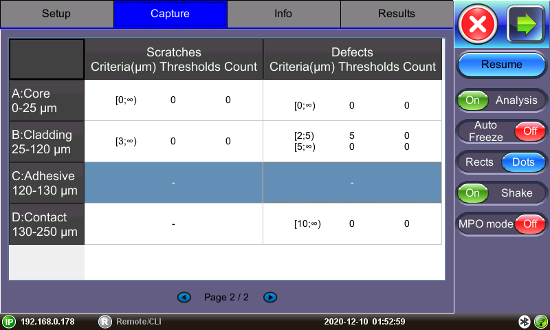
Pass/Fail IEC analysis table
(Measured scratches and defects compared with threshold criteria for each fiber layer)