MTTplus Quick Guide
The MTTplus Modular Test Platform addresses the challenges of communication service providers to increase efficiency and productivity. The flexible test platform lowers operational and capital expenditures associated with handling multiple technologies required to address today’s Access, Business, Metro, Carrier Ethernet, Transport and Core services.
The MTTplus platform is a modular test toolkit for wide ranging and evolving test needs.
MTTplus addresses the growing need of fiber test tools for the evolving hybrid FTTx / copper networks. Communication service providers can equip their field force with a test toolkit ranging from Ethernet, Internet, TDM transmission technologies as well as for FTTX/PON installation tools such as an Optical Power Meter and Fiber Inspection Scope.

MTTplus Test Modules
MTTplus SHDSL Test Module provides CPE installation, CO emulation pre-qualification, and IP/ATM services testing capabilities for service installation and verification. The module is based on the industry leading Lantiq SOCRATES chipset, offering best-in-class SHDSL performance and interoperability. SHDSL is ideal for business class services, enterprise networks, and industrial communications that must rely on legacy copper-based networks where fiber remains cost prohibitive. Utilizing SHDSL’s multiple pair bonding application enables robust data transmission over long copper lines.
The MTTplus-320 Multi-Service Module is a full-featured test solution for OTN, SONET, SDH, PDH, DSn, 64k Codirectional, C37.94, Carrier Ethernet, Fibre Channel, SyncE and CPRI/OBSAI.
The MTTplus-410+ Fiber Optics test module for the VeEX® MTTplus platform has up to 500,000 data points with 3 cm resolution. It supports a full range of test functions including OTDR, OPM, Light Source and VFL. GPS coordinates and images can be embedded into the OTDR sor files and PDF test report provided the MTTplus platform is configured with GPS and Camera options. Fiberizer® software for Windows® Desktop, Android™, and/or Apple® mobile devices is available to assist in data transfer, record management, and report generation for various VeEX fiber optics testers. View the Fiberizer webpage for more details.
The new MTTplus-420 GPON test module for the VeEX® MTTplus platform is designed for service activation at the ONT location. The unit checks optical power levels and non-intrusively decodes the messages exchanged between the OLT and ONT allowing technicians to perform advanced troubleshooting.
The MTTplus-522 Outside Plant (OSP)+ Expert Module combines key copper verification features with DSL/G.fast modem emulation. It is designed for Service Providers deploying broadband services over a DSL or G.fast access network.
The MTTplus-523 Module addresses key test requirements for IP based broadband services deployed over a G.fast or DSL Access network.
The now-discontinued MTTplus-900 WiFi Air Expert Module for the MTTplus platform is equipped with 802.11ac 3x3:3 WiFi capabilities to discover the network’s Access Points, Clients and Channels. It surveys coverage problems with signal, noise levels and utilization tracking. A dedicated spectrum analyzer assists in the troubleshooting of WiFi and non-WiFi interference affecting performance and the V-Perf function provides traffic Download/ Upload test to a wired Ethernet responder to evaluate the WiFi network’s capacity under load.
Basic Operations
Software Upgrades
To perform an MTTplus platform (system) software upgrade, insert a FAT32 USB memory stick, with the installer package, into one of the test set's USB ports and press the camera and power buttons simultaneously.

Platform and Module software upgrades can also be performed by pointing any standard web browser to the test set's IP address and selecting Platform Upgrade and Module Upgrade from the menu. The software upgrade packages can be downloaded from www.veexinc.com, or using the test set’s built-in VeExpress client software.
|
|
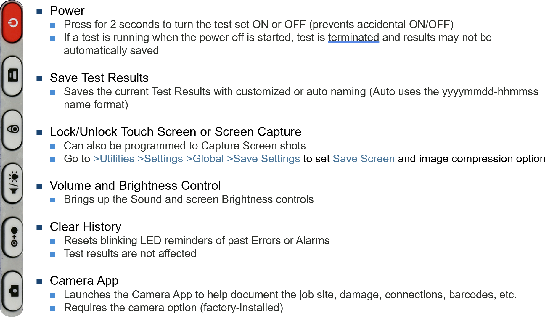
Turning the Test Set ON and OFF
-
Turn ON: Press and hold the red Power button for two seconds, until a confirmation tone is heard, and the power LED turns green (in noisy environments, refer to the power LED).
-
Turn OFF: Press and hold the red Power button for about two seconds, until two confirmation tones are heard. Then the shutdown process will start.
-
Forced Shut Down: In the rare case of a malfunction, our Customer Support team may instruct to press and hold the Power button for approximately four seconds, until the screen turns off. Results, data or configurations are not saved.
Power LED
A single LED indicates the power state of the unit.
-
OFF : The LED is off when the unit is powered off
-
GREEN: The LED is green when the unit is powered on and fully charged.
-
ORANGE: The AC/DC adapter is plugged in and the battery is charging.
Audible Beeps
Low Battery status is indicated by a periodic beeping sound, every four seconds, and displaying a warning pop-up message on the screen.
When working on battery power, once the charge capacity reaches about 10%, the test set will start beeping to notify users to plug in the AC/DC adapter. A pop-up message may also be presented on the screen. When the charge level reaches 5%, the test set automatically initiates the shutdown process, to protect the battery.
To get information about the amount of battery charge and autonomy estimate (under current usage condition) tap the battery icon displayed on the top-right corner of the screen.
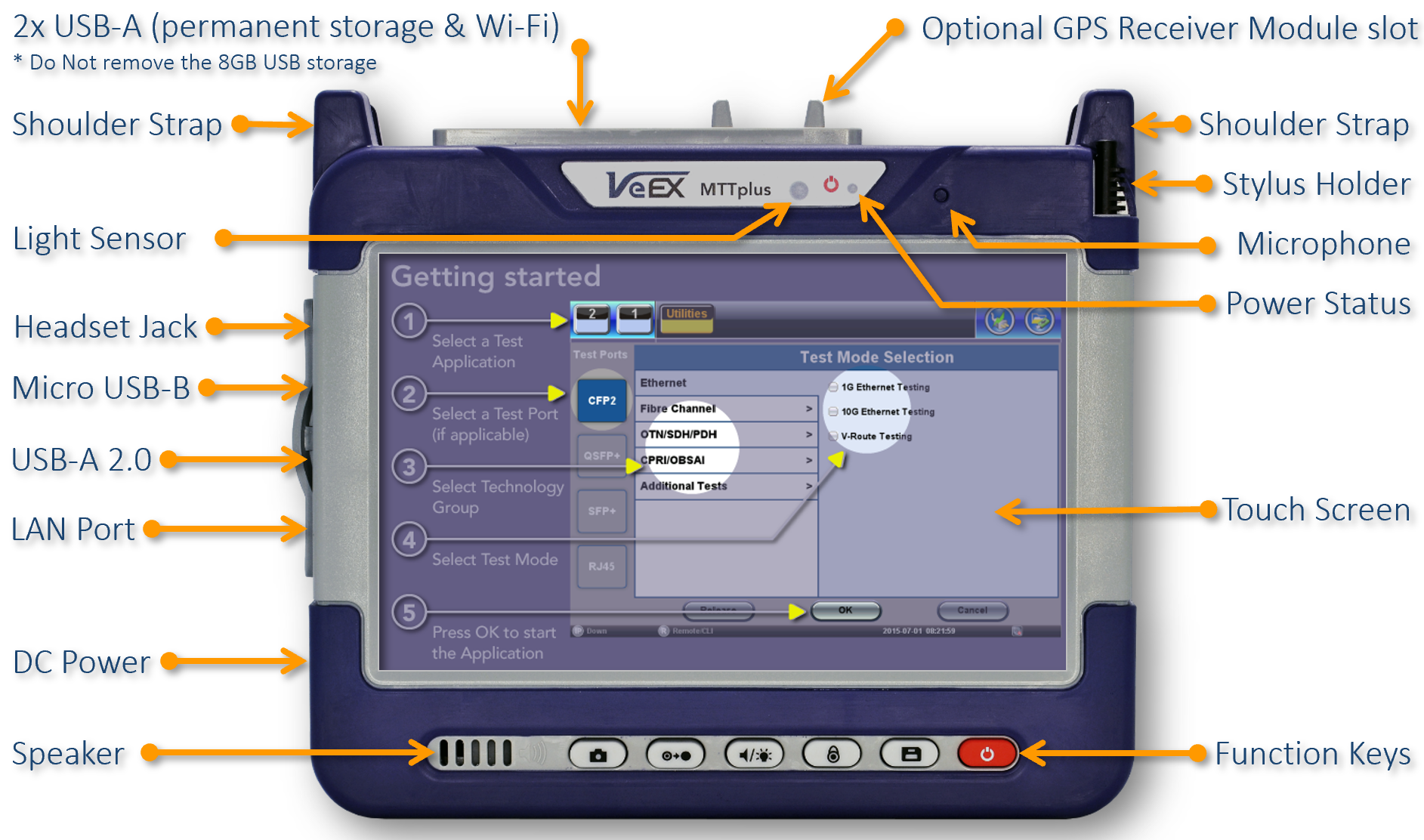
MTTplus Platform Interface

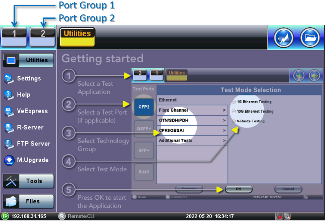
Quick Access Menus

Selecting a Test Mode (Technology or Function)
-
Select an empty Test App button. The Test Mode Selection menu is displayed. If applicable, select a Test Port.
-
Up to
-
Some test applications may require two port groups (e.g., router wrap-around test) and may not be supported by all test modules or test sets configurations.
-
-
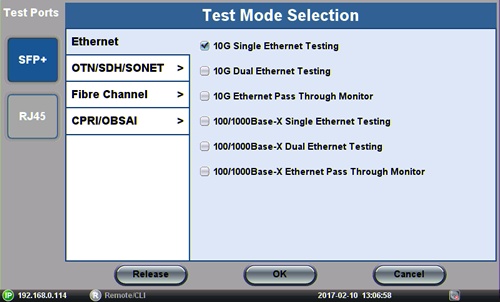
Protocol (technology group or link type), using the vertical tabs. (The available selection will depend on the capabilities of the selected port type.)
-
Test Application/Mode, using the check boxes. (The available test functions will depend on the of the selected protocol and purchased licenses.)
 If the Test Set shows a different Test Mode Selection menu, update its software to the latest version available using VeExpress or download the upgrade package from the product page on www.veexinc.com.
 -
Press OK to launch the Test Application
The test port is assigned to the selected test application and the required software/firmware is loaded.
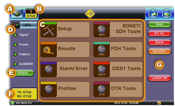
Understanding Common Test App GUI Elements
-
 System Utilities Button: Tap this button access
 -
 Active Test Application GUI: Shows the Test Port Group being used and the Test App ID (Rate/Technology)
-
Tap this button to release the Test App or change its Test Mode.
-
-
Test Application Menu
-
Lists all test Functions, Applications and Tools available for the selected test mode
-
Setup = Port and Test Signal configuration
-
-
LEDs - Test Signal Status
-
History - Clears past events reminder (blinking)
-
Current test interface line rates
-
Action buttons section
-
This vertical section displays direct access functions applicable to each specific Test Mode, such as Start/Stop test, Laser control, Error and Alarm injection, Start protocol capture, etc.
-
Most of these buttons offer immediate action. A few open a configuration menu.
-
Initial Settings
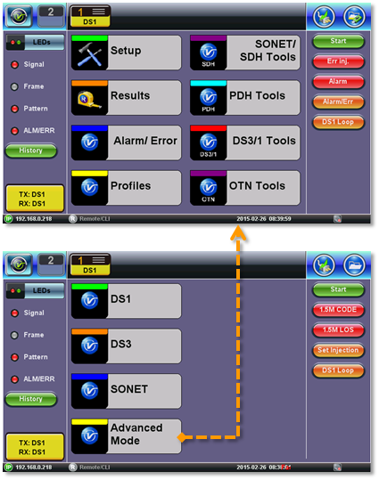
Before using the platform, set the language and user interface style as needed. By default, the user interface style is set to USA if the unit is shipped to North America and to International if the unit is shipped to outside USA and Canada.
To change the GUI language and user interface style:
-
Tap Utilities and then tap Settings.
-
Tap the Global option.
-
Select the language from the Language drop-down list box.
-
Select the user interface style from the User Interface drop-down list box.
-
International: Provides layer-based SDH/PDH configuration menus with access to detailed settings.
-
USA: Provides simplified application-based SONET/DSn menu with more automation. The Advanced Mode option displays the configuration menu for additional settings.
-
To manually change the Date & Time:
Go to System Tools >Utilities >Settings >Date & Time, to manually set the date, time and time zone. Then, tap Apply.
![]() To enable daylight saving time (DST), manually select a neighboring time zone with a +1:00 relative to the standard time zone of the current location. Set it back to the standard time zone offset when DST ends.
To enable daylight saving time (DST), manually select a neighboring time zone with a +1:00 relative to the standard time zone of the current location. Set it back to the standard time zone offset when DST ends.
Get Standard Time from GPS/GNSS
If equipped with the GPS/GNSS receiver (hardware option), manually copy the GPS time into the system.
Go to System Tools >Utilities >Settings >GPS/High Precision Clock, to configure the GNSS Receiver and turn it ON. Once it recovers time (ToD UTC) from the satellites, click the Sync ToD button to apply the standard time to the RTU. The standard time will be applied at the start of the next second (rise of the internal 1PPS timing signal). The local UTC Offset (Time Zone) setting is used to apply the correction for local time. This manual Sync ToD time setting function should not be used when NTP is enabled.
For more information on the atomic clock and relative phase monitoring, see High Precision Clock Sources and GNSS/GPS & Sky View.