Layer 4+ Applications
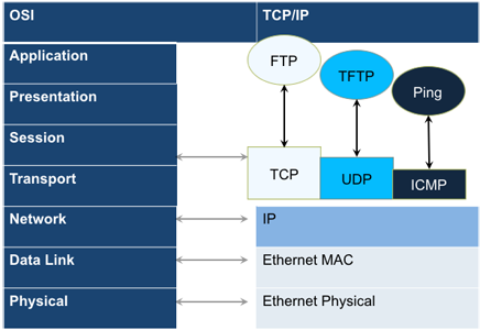
Layer4+ refers to the Internet layers 4 and above (transport and application layers), which are more closely related to the customers/subscribers’ applications and the way they use Ethernet, the Internet, and how they perceive performance (quality).
Stateful TCP testing refers to the validation of TCP connections used for the TCP/IP Protocol Stack. A V-Perf test will validate that the TCP parameters in the network were set up correctly. The optional V-PROBE is used as remote server to establish TCP connections and validate that the network is configured correctly for seamless passing of TCP traffic. It will also verify the maximum throughput for TCP traffic. Typically in the field, after running layer 2 & layer 3 tests successfully, a customer may still complain that their connection is slow to deliver their applications. Running a stateful TCP test will help verify maximum throughput rates in the download and upload direction. If throughput performance is poor, the test can help identify what the issue could be.
TCP Protocol and Overview
Fundamental TCP parameters are the ideal TCP Window Size and Throughput. The complete list of relevant measurements include:
- TCP Window Size
- TCP Throughput
- Number of Connections Established
- Download Time
- File Transfer Size
- Retransmits
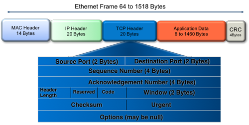
Transmission Control protocol is the most widely used transport layer protocol. TCP is used by most application protocols: HTTP, FTP, Telnet. It provides the following services:
- End-to-end connection
- Multiplexing/Demultiplexing of separate sessions
- Flow control
TCP is a connection-oriented protocol. A Connection is established prior to data transmission between the two end devices (client and server). A 3-way handshake procedure is used to establish connection.
When a connection is established, the data transfer can start. TCP uses sequence numbers to reassemble data and verify that no data has been lost.
TCP uses the Window mechanism for Flow Control:
- The Sender indicates in the Window size the data it is prepared to receive.
- The Window size is the amount of outstanding data that can be sent before acknowledgment is received.
- If data is lost, the window size is decreased and less data is sent prior to acknowledgment.

- Step 1: Client sends a SYN message with SYN flag set in the TCP header. The Sequence number specifies the number assigned to the first segment.
- Step 2: Server receives SYN packet and sends SYN + ACK packet SYN flag set, ACK flag set Sequence number specifies the server’s starting sequence number. Acknowledgment number means that the server has received X and expects X+1.
- Step 3: Client receives SYN + ACK and send ACK back. ACK number means that server has received Y and expects Y+1.
RFC 6349 is a practical testing methodology consisting of 4 different steps for measuring end-to-end TCP Throughput and Performance in a managed IP network.
- Step 1 Max MTU Search:
Search for the maximum packet length that can be sent through the network without segmentation. The Path MTU search follows RFC4821 (Packetization Layer Path MTU Discovery). - Step 2 Round Trip Time (RTT) Search:
Measure of the round trip time between the TCP segment sent and the acknowledgment received, the test has to be done in a network that is not congested to obtain the real round trip delay (not accounting for network buffer delay). - Step 3 Bottleneck Bandwidth (BB) Search:
For this step, a Layer2/3 test can be done (RFC2544 or Y.1564) to determine the maximum throughput rate supported by the network. - Step 4 Bandwidth Delay Product Calculation:
Based on RTT and BB results, the BDP is computed to estimate the optimal window size that should be used for testing (Auto mode). Fixed window size can also be specified.
Key Metrics:
- TCP Bandwidth Delay Product
- Transfer Time Ratio
- TCP Efficiency
- Buffer Delay
TCP Bandwidth Delay Product is the theoretical maximum of data that can be transmitted based on network delay and throughput rate.
![]() To completely occupy the available bandwidth the Window size must be set to the BDP value.
To completely occupy the available bandwidth the Window size must be set to the BDP value.
The ideal TCP transfer time is based on the Maximum achievable TCP transfer rate, calculated based on the Bottleneck Bandwidth (BB) and the layer 1-2-3-4 overheads associated with the network path. The actual TCP transfer time measures the time it takes to transfer data.
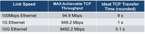
Example of an ideal TCP transfer time based on a 1500 Bytes size MTU and 100MB file download
TCP retransmission is done when TCP segments are lost during transmission or an acknowledgment is missing. Segments can be retransmitted more than once.
![]() There is no direct correlation between the number of Ethernet frames lost at the physical layer and the number of TCP retransmission, since a single lost acknowledgment could trigger many retransmission.
There is no direct correlation between the number of Ethernet frames lost at the physical layer and the number of TCP retransmission, since a single lost acknowledgment could trigger many retransmission.
The Buffer Delay represents the increase (or decrease) in Round Trip Time (RTT) during a TCP throughput test compared to the baseline RTT.
![]() A large RTT Buffer delay indicates that the network is experiencing congestion and that segments are being delayed.
A large RTT Buffer delay indicates that the network is experiencing congestion and that segments are being delayed.
Configuration
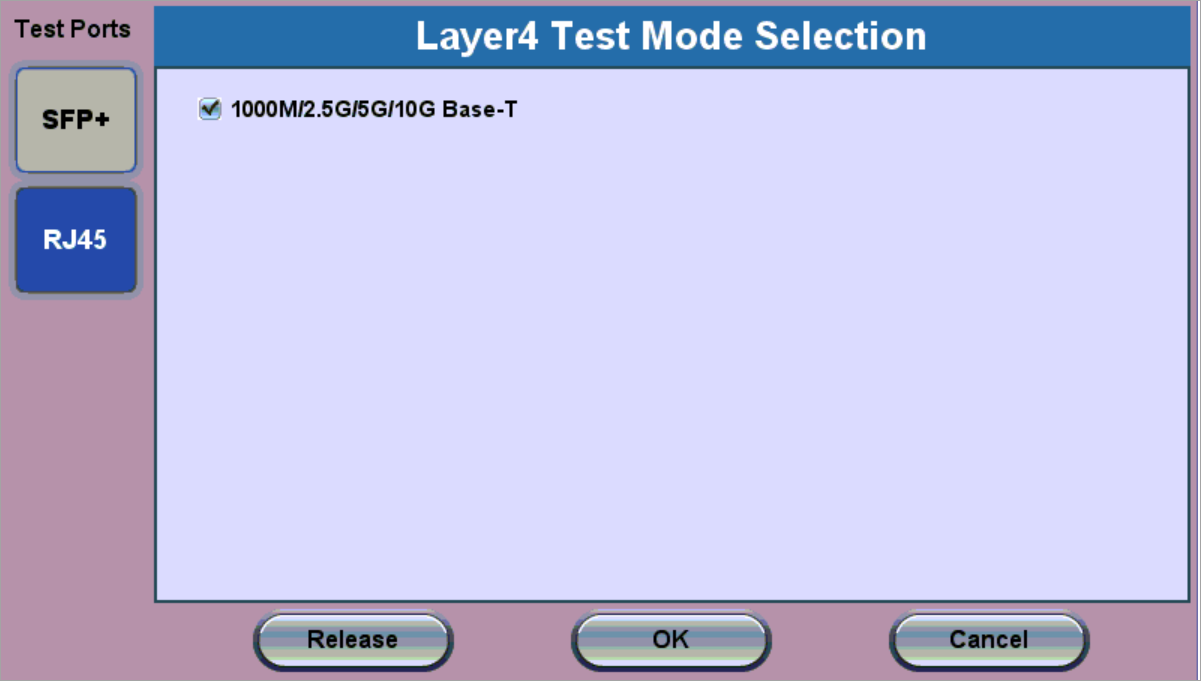
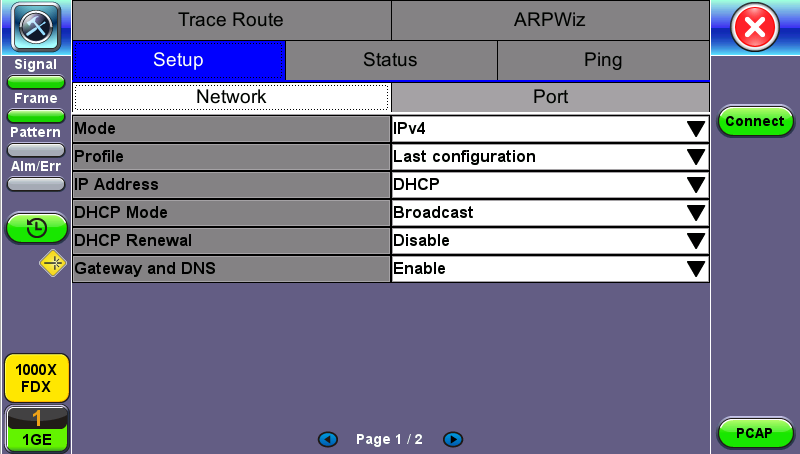
Before launching V-Perf, V-Test, or V-FTP tests, it's necessary establish an IP connection. For V-Perf testing, repeat these steps for both the far end and near end test sets.
By default, the test set starts in copper (RJ45) mode and it can detect 10GBASE-T, 5GBASE-T, 2.5GBASE-T, 1000BASE-T and even legacy 10/100BASE-T automatically.
- Select a Layer 4 test application to launch from the Test Mode menu.
- For testing on SFP ports, turn the laser on.
- Tap the IP icon. Configure a static IP address for testing. If the environment supports DHCP, select DHCP from the IP Address menu, then tap Connect.
- Once the proper IP information is entered, press Connect. An IP: PASS status indicates proper connection.
- Go to Layer 4+ Applications. The test application will load.

For more information about IP Connections, refer to IP .
Saving Test Results
Test results can be saved to the File Server using the Save hard key. Results can be retrieved via USB drive or remotely using the Web UI. Refer to File Manager.