OPM Test Mode

Selective (filtered) Optical Power Meters are used to measure the individual signal levels in Optical Distribution Networks (ODN) carrying multiple services, like in coexistent (CEx) PON deployments. Since there may be multiple wavelengths on the fiber being tested, traditional broadband OPMs DO NOT work in these environments.
Connection Process
Inspect and clean the test ports. Inspect and clean the fiber patch cord from the OLT and insert it into the test set OLT test port.
|
|
 Warning: Never look directly into the beam of an active optical source as this may result in harmful eye damage from radiation exposure.
Connect the test set at the customer premises between the ONT/ONU and the last splitter in the ODN. Do NOT connect the test set between the OLT and splitter without attenuation.
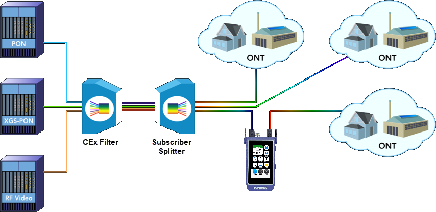
The test set will synchronize to the downstream frame (from the OLT) provided the OLT is operational and 1490/1577nm signal level is good. The downstream frame synchronization indicator should occur almost immediately.
To synchronize with the ONU, the test set needs to see the ONU registration process. Therefore, only connect the ONU AFTER the PON OPM application is already running. Otherwise, unplug and replug the ONU after the PON OPM application is running if the ONU is already connected to the test set.
 If the OLT and an active ONU are connected to the test set before starting the test application, the test set will not see the ONU activation and the above process will not be completed. In this instance, LOF will be reported for the upstream side; no ONU ID or ONU S/N information on the OPM results page will be displayed.
Once connected to the OLT, swipe-down from the top to reveal the Test Application menu and select PON OPM.
A selective (filtered) optical power meter (OPM) separates coexistent G-PON 1490 nm and XGS-PON 1577 nm downstream wavelengths, to simultaneously measure their individual optical power levels. These measured signal levels can be compared against standard (or customized) minimum and maximum thresholds expected for different network points to diagnose if the physical link passes or fails the applicable installation requirements. Verify the ONU-ID and Serial Number and ONT status upon completion of ONU activation. If laser instability is suspected, monitor the signal/ODN loss budget graph to verify signal stability over time.
OPM Setup
On the GPON/XGSPON Summary screen, swipe up to show the GPON menu.
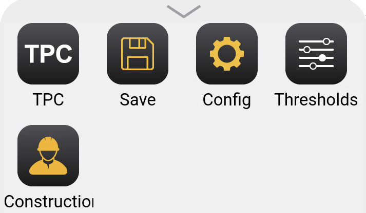
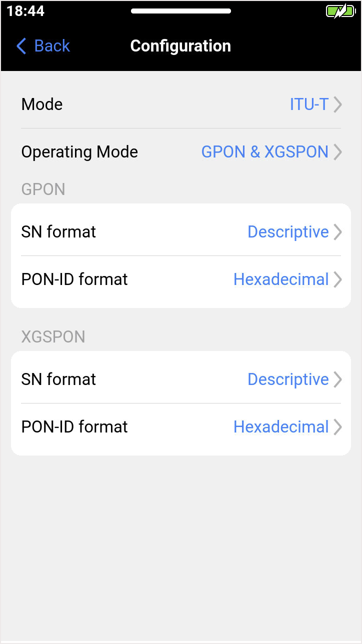
Select  Config to set up the test mode (GPON, XGS-PON, EPON, 10G-EPON) and format of PON ID and serial number.
The OPM allows the configuration to measure power from G-PON/EPON's 1490 nm, XGS-PON/10G-EPON's 1577 nm or both wavelengths, as well as to enable or disable the Pass/Fail Thresholds evaluation. Select  Thresholds to set the PASS/FAIL Thresholds based on the ITU-T and IEEE Test standards or customize a unique profile.
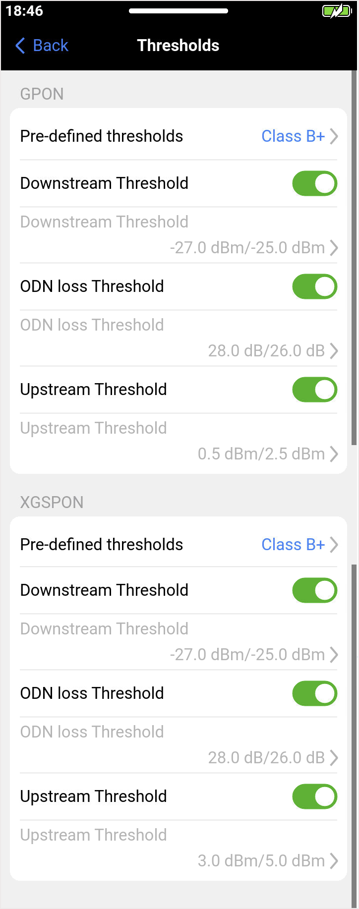
See PON Optical Distribution Network (ODN) Classes for information on GPON/XGS-PON Threshold Standards.
When thresholds are enabled, tap on the G-PON or XGS-PON fields to configure the Site (ONT or OLT location) and transmitter Class. Users can select standardized thresholds, based on transceiver classes for G-PON (A, B, B+, C, C+, Ext D) or XGS-PON (N1, N2, E1, E2, B+, C+), or enter custom limits by selecting User.
To modify the custom threshold values, select User then tap ⟨ Back. Select the corresponding field to display the Downstream, ODN loss, and Upstream thresholds.
Slide the markers left and right to adjust, or tap the boxes to directly enter the desired maximum and minimum values in dB or dBm, for the signal power level limits allowed.
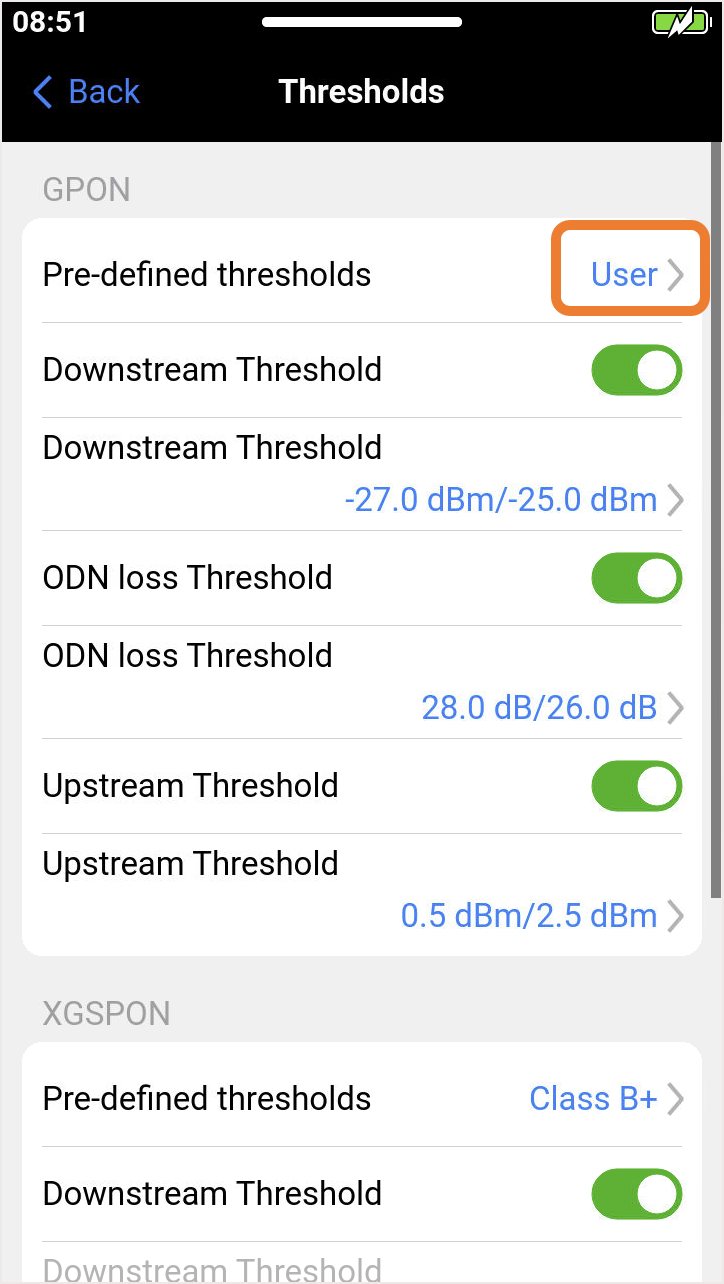
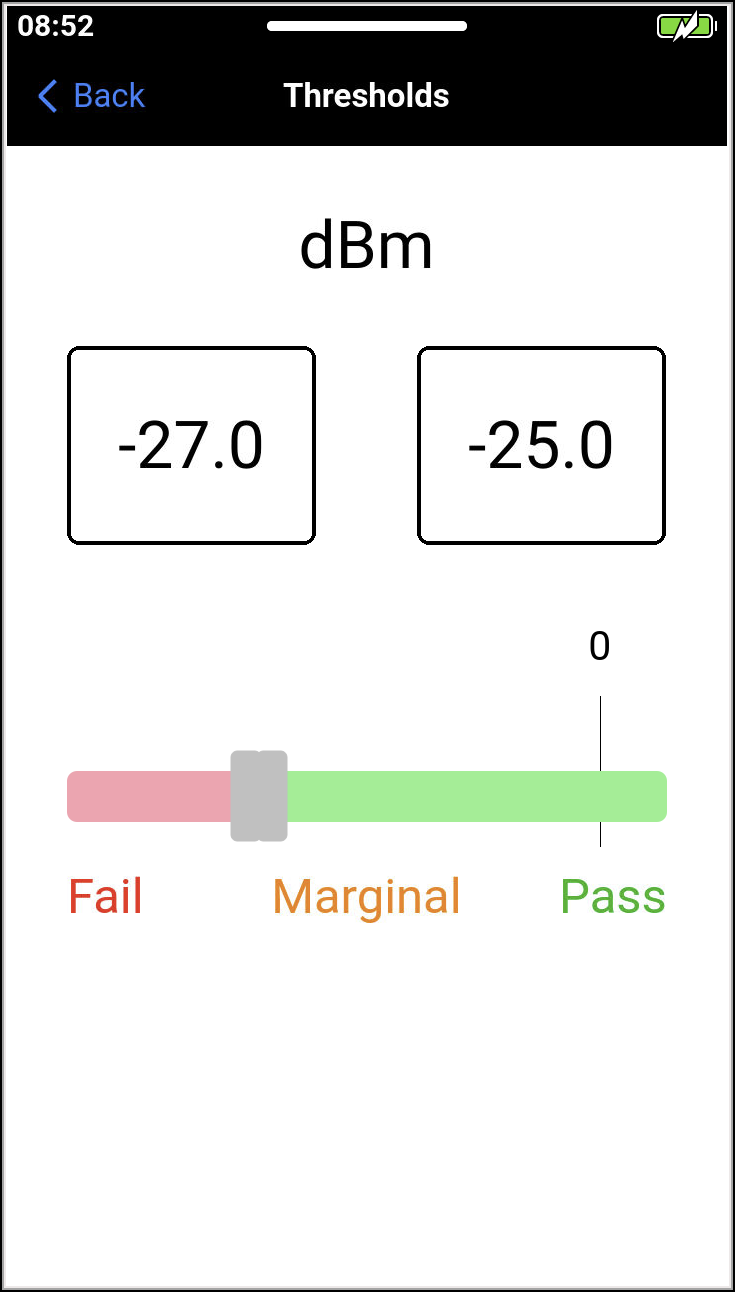
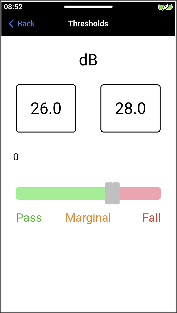
Tap the ⟨ Back arrows to return to the previous screen.
Optical Power Measurement Results
Contrary to common Broadband OPMs, which don't discriminate between the optical signals coming in, a Selective PON OPM WILL NOT measure signals outside of its working bands (e.g., 1490 nm for 1G, 1577 nm for 10G) and it will display Low or very attenuated values for any other wavelengths that may be present in the fiber under test.
Certain optical distribution networks carry a TV Broadcast signal over the 1550 nm wavelength, however, that does not affect the accuracy of the GPON and XGS-PON level measurements, when the right selective OPM is being used.
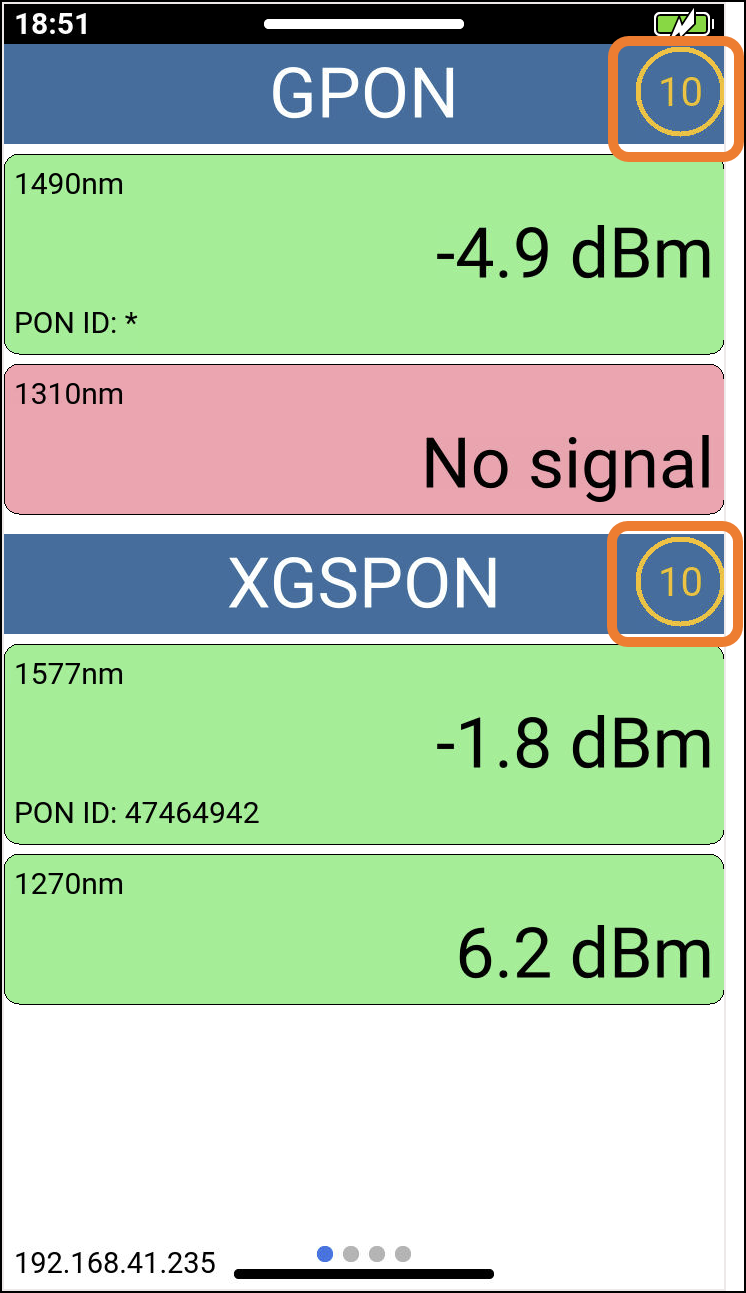
The GPON/XGSPON Summary screen shows the PON ID and optical power levels for both GPON and XGS-PON modes.
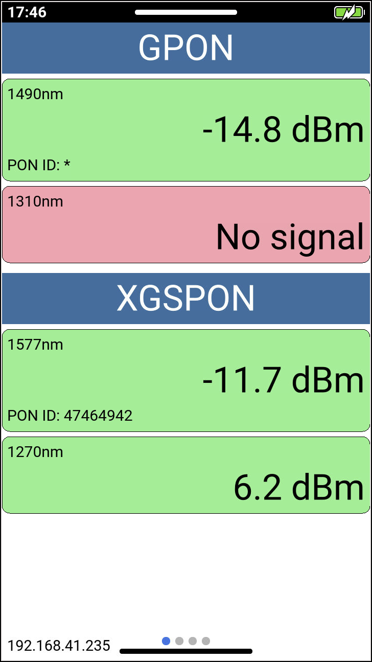
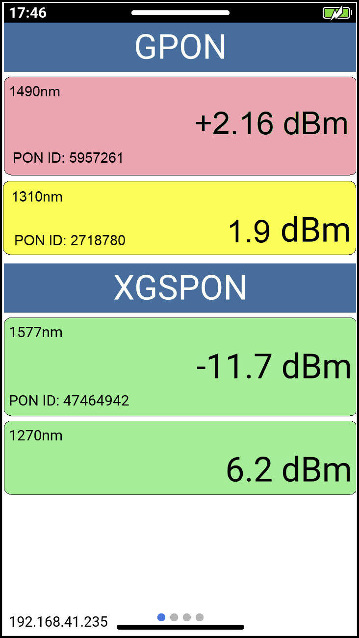
Optical power levels that fail the minimum or maximum thresholds are shown in red. Levels within the expected threshold limits will be in green. Low levels are shown in yellow. If no signal is detected, the test set displays No signal in red.
Histogram and ODN Loss History
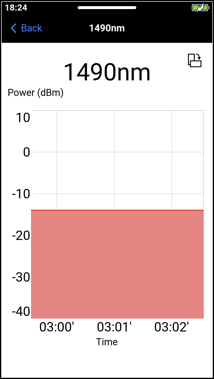
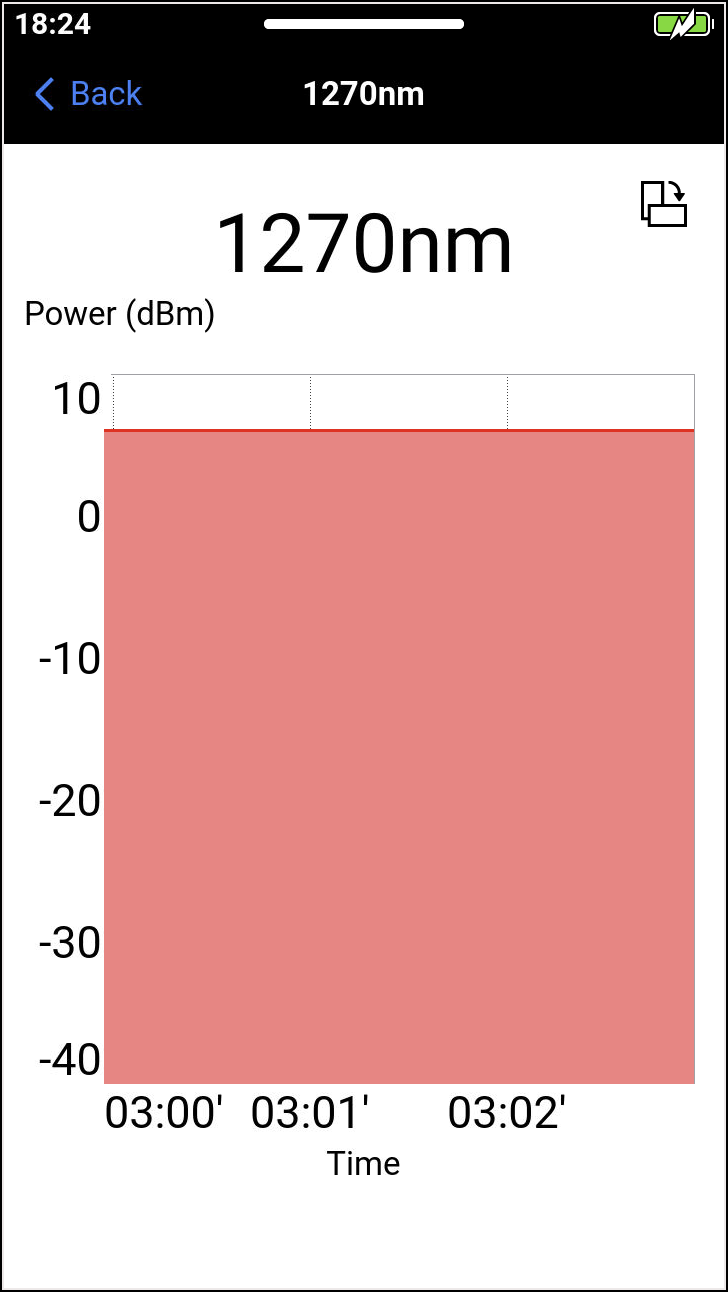
Tap the power level measurement to view the corresponding Histogram and monitor upstream and downstream signals. Tap  to open the graph in a horizontal view, and tap
  to return to the previous view.
Test Point Compensation (TPC) for Attenuation Adjustment
Using an attenuator with TPC helps protect the receiver from high input power while maintaining accurate power readings.
Test Point Compensation (TPC) automatically adjusts for the attenuator by subtracting its impact from the measured power levels. This ensures that displayed measurements reflect the actual signal strength, even when attenuation is applied.
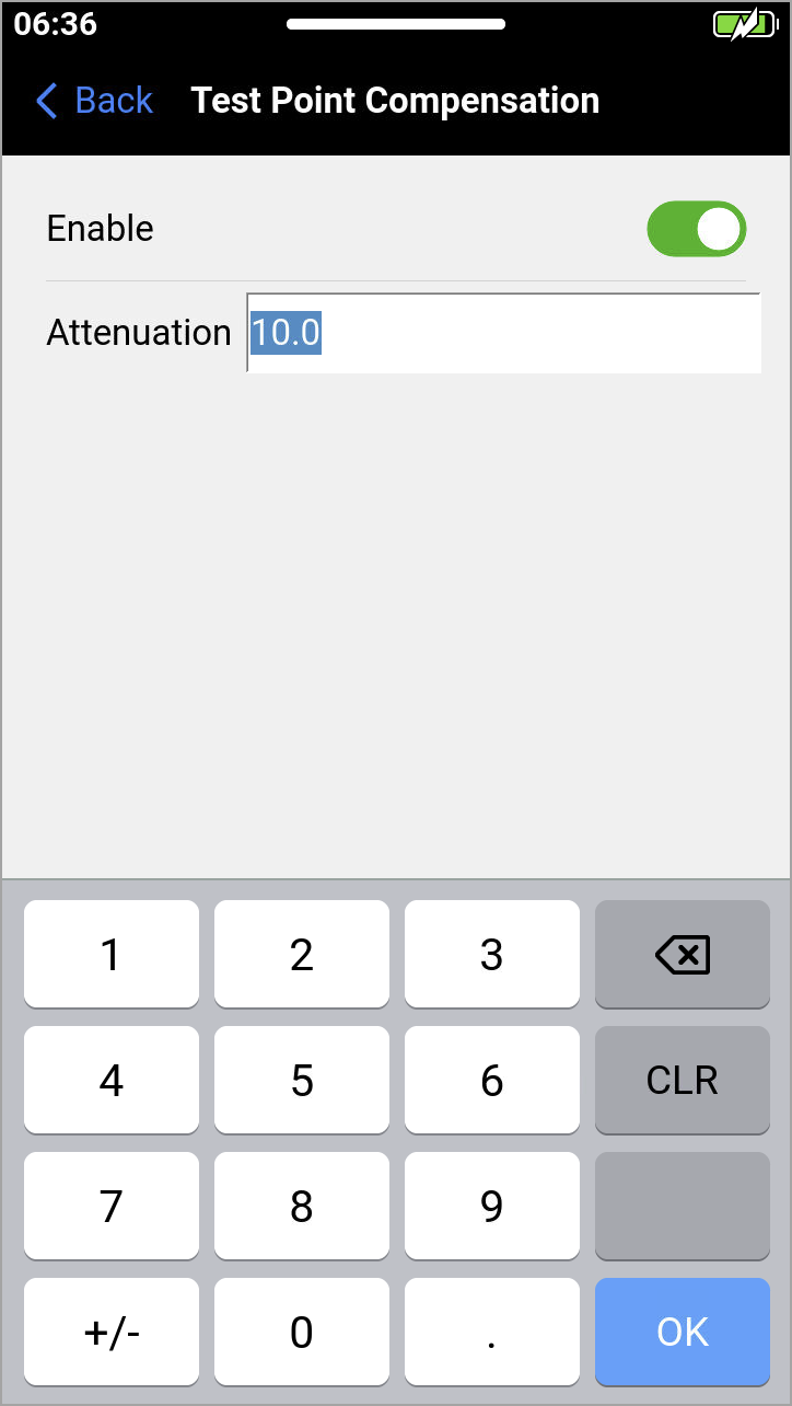
Enable TPC in the settings to ensure precise measurements when testing with an attenuator in the signal path. To enable TPC, swipe up from the bottom to reveal the Function menu.
-
Tap
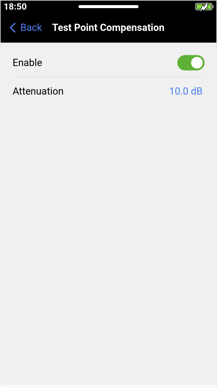
 Test Point Compensation and toggle on Enable.
 -
Tap
 to type and set the level of the attenuator you have in place.
 -
Look for the indicator
 that is displayed on the main screen. All values are now adjusting for the attenuation and subtracting the impact of it.