Header Settings
- BERT Profile: Load a previously configured test profile or create a new profile from existing settings.
- Encapsulation Type: None, Provider Backbone Bridge (PBB-TE), or Multiprotocol Label Switching (MPLS-TP). MPLS-TP is a simplified version of MPLS. Provider Backbone Bridge MAC-in-MAC (IEEE 802.1ah) encapsulation are configured trunks that add resiliency and configurable performance levels in the provider backbone network. Both options are available for 1GE Copper/Fiber and 10GE port for all Ethernet tests (Layer 2,3 and 4) - BERT, RFC2544, Throughput, V-SAM.
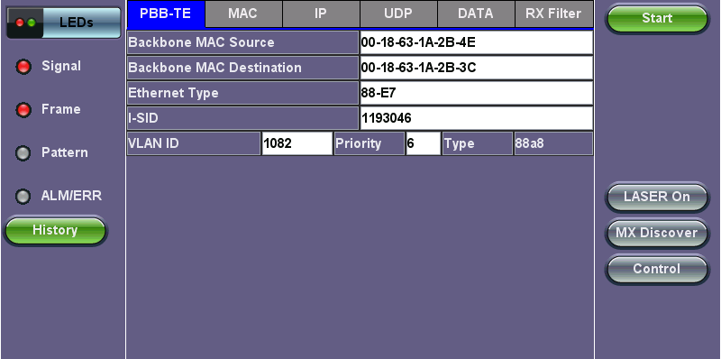
Tap the PBB or MPLS-TP block to configure the settings. All fields are configurable.
- Backbone MAC Source.
- Backbone MAC Destination.
- Ethernet Type.
- I-SID.
- Backbone VLAN ID, Priority, Type.
MPLS-TP:
- MPLS-TP MAC Source.
- MPLS-TP MAC Destination.
- Ethernet Type.
- VLAN ID, Priority, Type.
- LSP, PW, CW .
PBB
- Test: Select the test layer to perform the BERT
.
- Options are Layer 1 Unframed, Layer 1 Framed, Layer 2, Layer 3, and Layer 4.
- Frame Type: Select the Ethernet frame type for Layer 2 or Layer 3
.
- 802.3 Raw (IEEE 802.3 frame without LLC) - Not available when Layer 3 is selected .
- 802.3 LLC (IEEE 802.3 frame with LLC header) .
- 802.3 SNAP (IEEE 802.3 frame with SNAP header).
- Ethernet II (DIX) (named after DEC, Intel, and Xerox, this is the most common frame type today).
- MAC/IP: Tap the MAC and IP blocks on the Frame image to access the setup menus
.
- Set the Source and Destination MAC address for Layer 2.
- Set the Source and Destination MAC and IP addresses for Layer 3 and Layer 4.
- VLAN: Off, 1 tag, 2 tags, 3 tags
.
- The user is able to configure up to 3 VLAN tags (VLAN stacking, for Q-in-Q applications).
 VLAN stacking is an option.
- The user is able to configure up to 3 VLAN tags (VLAN stacking, for Q-in-Q applications).
- MPLS: Off, 1 tag, 2 tags, 3 tags
.
- The user is able to configure up to 3 MPLS tags. MPLS tag configuration is only available when the MPLS option is purchased.
- The user is able to configure up to 3 MPLS tags.
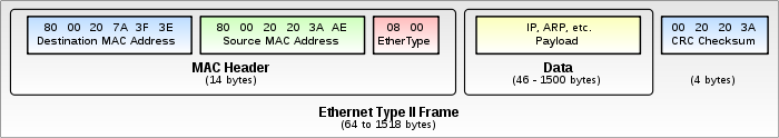
The most common Ethernet Frame format, Type II
MAC, VLAN, MPLS, IP, and Test Pattern Configurations
To configure the MAC addresses, IP addresses, VLAN tag(s), MPLS tag(s), and test pattern, tap on the frame image displayed on the screen. This brings up the configuration screens for all the header fields.
- MAC Header Tab:
- MAC Source: Use the default source address of the test set or configure a new or different address.
- MAC Destination: Configure the destination MAC address of the far-end partner test set or use the ARP or ARP GW keys to determine the MAC address of the destination IP address (ARP) or the Gateway (ARP GW).
A valid IP connection needs to be up to use these functions. Refer to IP Connections.
Port setup and IP connection are required prior to performing the following Ethernet applications: Ping, Trace Route, Web/FTP, ARP Wiz, VoIP, IPTV testing, and 1388v2 (except Layer 2).
Tap IP from the Ethernet home menu to access Port and IP settings.
- Ethernet Type: For Layer 2 testing, the user can also configure the Ethertype:
- 0800-IP (Internet Protocol Version 4, IPv4).
- 0600-Xerox.
- 0801-X.75 (X.75 Internet).
- 0805-X.25 (X.25 Level 3).
- 0806-ARP (Address Resolution Protocol [ARP]).
- 8035-RARP (Reverse Address Resolution Protocol [RARP]).
- 8137-IPX (Novell IPX).
- 814C-SNMP.
- 8847-MPLS unicast.
- 8848-MPLS multicast.
- 86DD (Internet Protocol, Version 6 [IPv6]) - Future Release.
Tap on Mac Source, ARP, and ARP Gateway buttons to populate the fields with default test port settings.
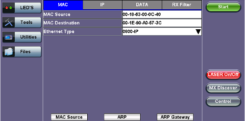
BERT Setup - MAC address settings (Layer 3)
- VLAN Tab: In the VLAN tab the following parameters are configured:
- VLAN ID: Configurable in the range 1 to 4094.
- VLAN ID is the identification of the VLAN, which is basically used by the standard 802.1Q.
- It has 12 bits which allows the identification of 4096 (2^12) VLANs.
- Of the 4096 possible VIDs, a VID of 0 is used to identify priority frames and value 4095 (FFF) is reserved.
- Maximum possible VLAN configurations are therefore set to 4094.
- VLAN Priority: Configurable in the range 0 to 6
.
- Set by the Priority Code Point (PCP), a 3-bit field which refers to the IEEE 802.1p priority.
- It indicates the frame priority level from 0 (lowest) to 7 (highest), which can be used to prioritize different classes of traffic (voice, video, data, etc.).
- Type: The following selections are possible:
- 8100 (IEEE 802.1Q tagged frame).
- 88a8 (IEEE 802.1ad Provider Bridging).
- Drop Eligible: If enabled, drop eligibility flag will be set.
- VLAN Flooding: Enable/Disable.
- VLAN Flooding Range: Specifies the number of VLAN IDs. Enter a number from 0-4096. The VLAN IDs will be incremented by 1 until it reaches the number of times entered in the flood range.
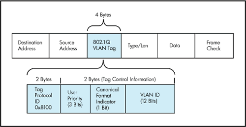
IEEE 802.1Q VLAN Tag in an Ethernet Frame
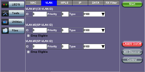
BERT Setup - VLAN Tag configuration (Layer 3)
- MPLS Tab: In the MPLS tab the following parameters
are configured:
- MPLS label: Configurable in the range 16 through 1,048,575 (labels 0 to 13 are reserved). Composed of 20 bits which allows for the creation of over one million labels.
- CoS: Configurable in the range 0 to 6. This field is three bits in length and maps directly to IP Precedence TOS bits to provide Class of Service (COS).
- S-bit: Configurable 0 or 1. The S field is one bit in length and is used for stacking labels. This is important as it is used to indicate the last label in the label stack.
- TTL: Configurable in the range 0 to 255. The default setting is 128 hops. Used to decrement the time-to-live counter.
- MPLS label: Configurable in the range 16 through 1,048,575 (labels 0 to 13 are reserved).
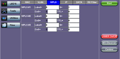
BERT Setup - MPLS label configuration
- IP Tab: In the IP tab the user must configure the destination IP address and source address. The user may also configure the following IP header fields:
- IP Type: IPv4 .
- IP Src and IP Dest: For IP Src, if the IP connection is up, refer to IP Connection. The source address is fixed to the IP address from the IP setup menu.
- IP TOS (for Quality of Service testing):
- Legacy TOS (Precedence): The first three bits of the IP TOS field can be edited:
000 - Best Effort
001 - Bulk Data
010 - Transactional
011 - Call Signaling
100 - Streaming Video
101 - Voice
110 - Routing
111 - Reserve - DSCP (Differentiated Services Code Point): The first six bits of the IP TOS can be edited to provide more granular service classification.
For more information on the definition of DSCP field in IPv4 and IPv6 headers, refer to RFC2474. - Time To Live (TTL): Configurable in the range 0 to 255.
- Fragment offset byte: Configurable in the range 0 to 65.528.
The fragment offset field, measured in units of eight-byte blocks, is 13 bits long and specifies the offset of a particular fragment relative to the beginning of the original unfragmented IP datagram. - Protocol field: UDP (0x11), TCP (0x06), User Defined.
- Legacy TOS (Precedence): The first three bits of the IP TOS field can be edited:
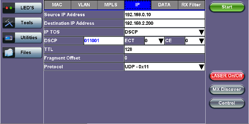
BERT Setup - IP Address settings (Layer 3)
- Data Tab: User selects a test pattern that will be encapsulated in the Ethernet frame payload (for framed mode).
Depending on the test layer, different test pattern options are available. -
Layer 1 Framed Test Patterns
-
CRPAT: Compliant Random Pattern provides broad spectral content and minimal peaking for the measurement of jitter at component or system level.
-
CJTPAT: Compliant Jitter Test Pattern is a Jitter Tolerance Pattern that stresses a receiver by exposing it to extreme phase jumps thereby stressing the clock data recovery (CDR) circuitry. The pattern alternates between repeating low transition density patterns and repeating high transition density patterns.
-
CSPAT: Compliant Supply Noise Pattern. Represents worst case power supply noise.
-
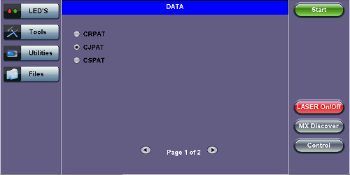
BERT Setup - Data selection (Layer 1 Framed)
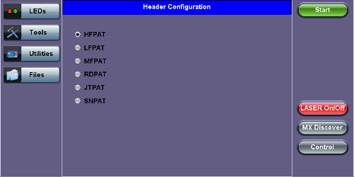
BERT Setup - Data selection - (Layer 1 Unframed)
-
Layer 1 Unframed Test Patterns
-
HFPAT (High Frequency Pattern): This test pattern is to test random jitter (RJ) at a BER of 10-12, and also to test the asymmetry of transition times. This high frequency test pattern generates a one, or light on, for a duration of 1 bit time, followed by a zero, or light off, for a duration of 1 bit time. This pattern can be generated by the repeated transmission of the D21.5 code-group. Disparity rules are followed.
-
LFPAT (Low Frequency Pattern): The intent of this test pattern is to test low frequency RJ and also to test PLL tracking error. This low frequency test pattern generates a one, or light on, for a duration of 5 bit times, followed by a zero, or light off, for a duration of 5 bit times. This pattern can be generated by the repeated transmission of the K28.7 code-group. Disparity rules are followed.
-
MFPAT (Mixed Frequency Pattern): The intent of this test pattern is to test the combination of RJ and deterministic jitter (DJ). This mixed frequency test pattern generates a one, or light on, for a duration of 5 bit times, followed by a zero, or light off, for a duration of 1 bit times, followed by a one for 1 bit time followed by a zero for 1 bit time followed by a one for 2 bit times followed by a zero for 5 bit times followed by a one for 1 bit time followed by a zero for 1 bit time followed by a one for 1 bit time followed by a zero for 2 bit times. This pattern can be generated by the repeated transmission of the K28.5 code-group. Disparity rules are followed.
-
RDPAT (Random Data Pattern): Designed to provide energy across the entire frequency spectrum providing good simple BER testing.
-
JTPAT (Jitter Tolerance Pattern): Designed to verify jitter tolerance on the receivers by exposing a receiver's CDR to large instantaneous phase jumps. The pattern alternates repeating low transition density patterns with repeating high transition density patterns.
-
SNPAT (Supply Noise Pattern): Designed to simulate the worst case power supply noise that could be introduced by a transceiver.
-
- Layer 2, 3, & 4 test patterns
- PRBS:
- 2^31 -1 (147 483 647-bit pattern used for special measurement tasks, [e.g., delay measurements at higher bit rates]).
- 2^23 -1 (8 388 607 bit pattern primarily intended for error and jitter measurements at bit rates of 34 368 and 139 264 kbps).
- 2^13 -1 (32 767 bit pattern primarily intended for error and jitter measurements at bit rates of 1344, 2048, 6312, 8448, 32 064 and 44 736 kbps).
- 2^11 -1 (2047 bit pattern primarily intended for error and jitter measurements on circuits operating at bit rates of 64 kbps and N x 64 kbps).
- Fixed: All 0s or All 1s
- User Defined pattern: Length depends on size of frame.
- Inversion: Normal or inverted.
- PRBS:
BERT Setup - Data selection - PRBS Patterns (Page 1)
- Auto (Special Patterns): For special patterns, the most significant bit of the test pattern is populated first into the payload frame, as opposed to non-special patterns, in which the least significant bit is populated first.
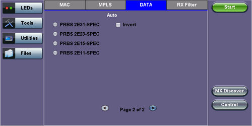
BERT Setup - Data selection - Special Patterns (Page 2)
-
RX Filter Tab:
Allows the user to filter incoming streams. When checked, the incoming traffic flows not matching these criteria will not be considered for these results.-
MAC Destination address
-
MAC Source address
-
VLAN
-
VLAN Priority
-
VLAN Eligible
-
Frame Type
-
Type of Service
-
Protocol Type
-
IP Destination address
-
IP Source address
-
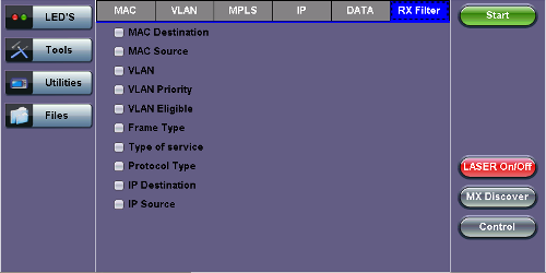
BERT Setup - RX Filter selection
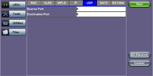
- UDP/TCP Tab: Input Source Port and Destination Port.
BERT Setup - RX Filter selection