Connecting the Fiberscope
![]() Use an USB-A OTG cable (optional with purchase) to connect a USB to the micro-B USB port. The port supports memory drives and USB add-on devices such as fiberscopes.
Use an USB-A OTG cable (optional with purchase) to connect a USB to the micro-B USB port. The port supports memory drives and USB add-on devices such as fiberscopes.
![]() OPTICAL SAFETY
OPTICAL SAFETY
-
Deactivate the laser before connecting or disconnecting optical cables or patchcord.
-
Never look directly into an optical patchcord or optical interface while the laser is enabled. Exposure to optical radiation for an extended period can caused irreparable damage to eyes.
-
Never use a fiber microscope to check the optical connectors when a laser source is active.
The operator is assumed to have received basic training in fiber optics and related testing and measurement practices.
Read the Safety Information before beginning using optical features of the test set.
![]() Fiber Scope image view requires the Fiber Scope Expert option to be enabled on the chassis/platform except for the VS500 which can already include this option. This can be confirmed by viewing the device ID is either -1500 or -2500.
Fiber Scope image view requires the Fiber Scope Expert option to be enabled on the chassis/platform except for the VS500 which can already include this option. This can be confirmed by viewing the device ID is either -1500 or -2500.
Attach the DI-1000/DI-1000MPO/DI-3000
Attach the fiberscope to an available USB Type-A interface on the test set.
![]() Older analog fiberscopes require a USB adapter.
Older analog fiberscopes require a USB adapter.

When the DI-1000, DI-1000MPO, or DI-3000 are powered, they will emit a blue LED. Select the tip that best matches the connector endface that is to be inspected. For more information about available connector tips, see the DI-1000 Digital Fiber Inspection Microscope Adapter Tips Guide on www.veexinc.com.
After powering on and setting up the fiberscope, select the tip that best matches the connector endface that is to be inspected.
Scope tips are secured in place with a locknut. There is a slot (specialty tips may have more than one slot) that will ensure the tip is aligned properly to the top of the fiberscope prior to securing the locknut. Attach a tip by rotating the locknut clockwise (tip faced away). Remove a tip by rotating the locknut counterclockwise (tip faced away). With the correct tip fastened and secured, launch the Fiberizer application (PC, mobile, VeEX test set) and plug into an available USB interface or connect to the WiFi network.
Rotate the round focus knob to manually bring the image into focus. For the DI-3000 scope, a built-in autofocus button can also be used.
Once the fiberscope is detected, tap Yes in the pop-up window to enter the Fiberscope menu.
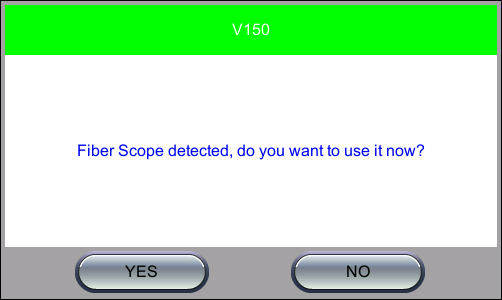
Fiber Scope Detected Message
Alternatively, select the Test Application icon > Utilities > Fiber Scope.
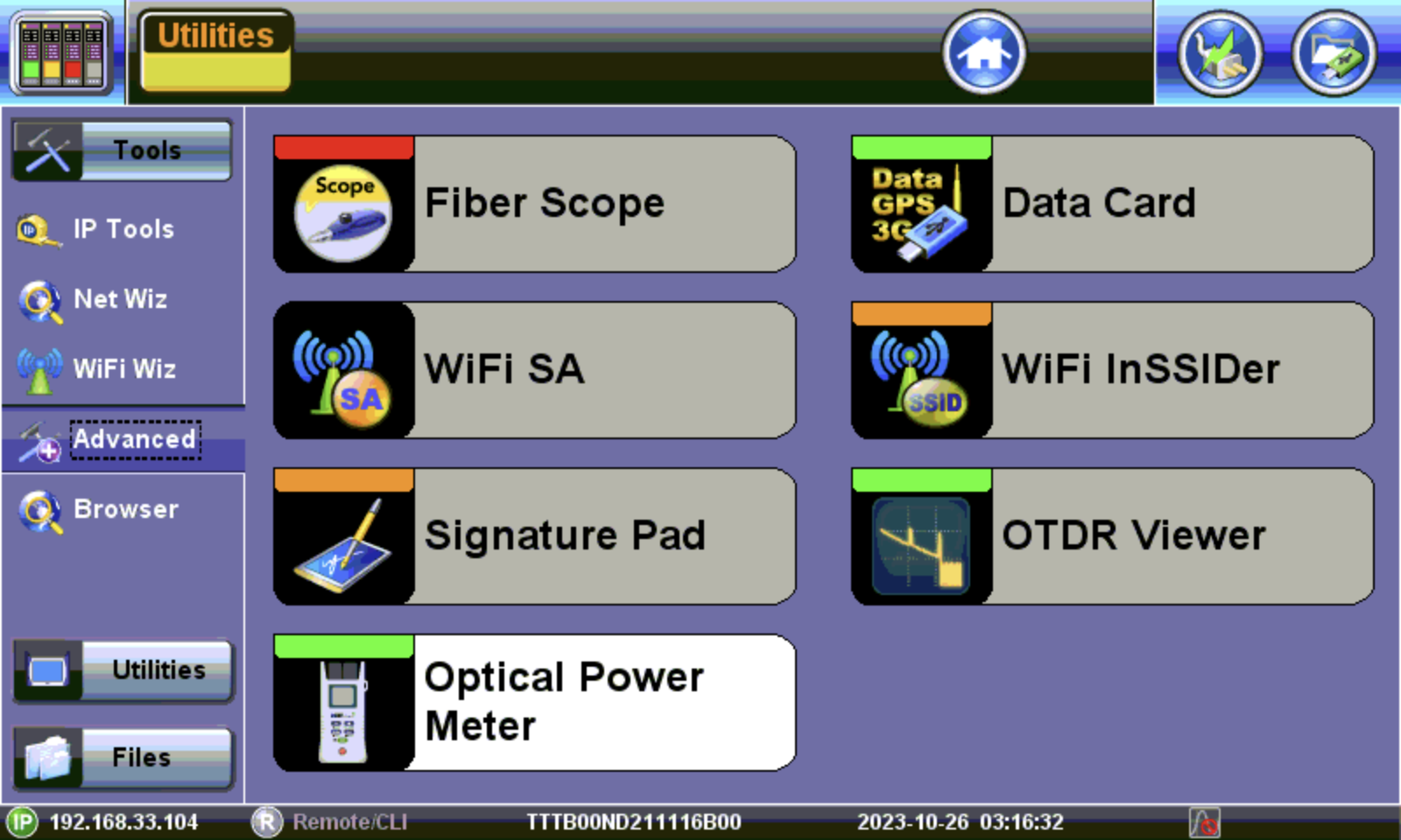
Fiber Scope, located in Tools > Advanced menu
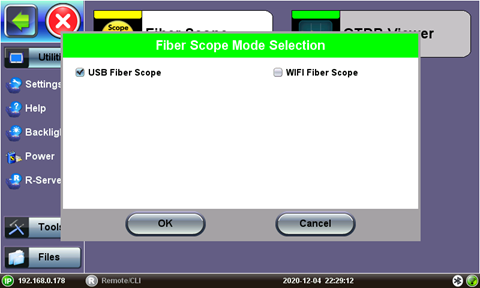
Fiber Scope Connection Mode Selection (USB for direct connection, Wi-Fi for DI-3000 AP)
Select the USB Fiber Scope checkbox for wired fiberscopes, such as the DI-1000, DI-1000MPO, VS500 (discontinued), or DI-3000 via USB.
Select WiFi Fiber Scope to initiate a scan for an available DI-3000. Refer to Wi-Fi Wiz for more information on setting up a WiFi Access Point if automatic scanning fails.
|
|