GNSS/GPS & Sky View
GNSS Receiver Settings and Operation
This section explains the GNSS Receiver configuration and basic settings required to quickly verify proper module installation and operation. Refer to the tables at the end of this document for application-oriented settings.
-
Install the portable antenna facing up, on a stable surface or mounting, with a wide unobstructed view to the sky or use a professionally-installed in-building roof-top antenna feed.
-
Connect the active GPS or antenna to the GNSS Receiver module’s SMA connector. If a BNC-to-SMA or TNC-to-SMA adapters is required, use flexible adapter cables (not rigid adapters) to prevent any mechanical stress.
-
Turn the GNSS Receiver = ON.

GNSS Receiver On
-
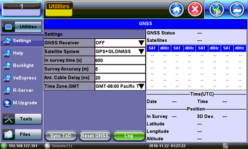
Go to >Utilities >Settings >More >High Precision Clock >GNSS.
-
Set the Satellite System = GPS
-
Set In-survey time (s) = 600, which is the time window used by the GNSS Receiver to assess stable location, using the specified accuracy (below). Having an accurate tri-dimensional location is required to calculate accurate time.
-
Set In-survey accuracy (m) = 5, which is a target of <5m for the Mean V accuracy reading. Smaller values tighten the location accuracy requirements, but the site survey process may take longer. It is possible to get better than 1.5m location accuracy when using professionally-installed roof-top antennas.
-
Enter any antenna cable delay that needs to be compensated for (velocity of propagation is cable dependent, their values are around 5ns/m or 1.2ns/ft). Enter 20ns if using the 5m portable antenna.
-
Select the Time Zone Offset (it is used to calculate the local time of day).
-
Wait for GPS Status on top to show Lock and the
 icon at the bottom of the screen turns green. It indicates that it is successfully tracking enough GPS and GLONASS satellites.
 -
Wait for about 15 to 30 minutes for the Mean V value to be below 5.00m and until the In Survey status also shows Locked. This indicates that the GPS position has reached the required accuracy (site survey finished) and that it has switched into Timing Mode.
-
At this point, the GPS Module should be providing accurate Time and Timing (1PPS).
-
Tap the Sync ToD button to synchronize the test set’s (system) real-time clock.
Atomic Clock Settings and Operation
This section explains the different disciplining parameters for the optional chip-scale Atomic Clock and provides the settings required to quickly verify its proper operation. For application-oriented configurations, please refer to the suggested configurations table at the end of this document.
Free Running Stage (Frequency only)
By default, the built-in Atomic Clock oscillator starts in free-running mode, providing a calibrated Atomic 10MHz frequency reference. (Its exact frequency could vary over time due to ageing, temperature, storage and other factors.) It also produces an arbitrary (non-traceable) 1PPS timing signal that is not aligned to the standard UTC second. Disciplining must be used in order to make the necessary frequency and timing corrections.
Oscillator Disciplining Process (Frequency & Phase)
The disciplining process acts as a continuous “soft calibration” that corrects any frequency deviation in the oscillator and aligns the timing pulse (1PPS) to the standard UTC second. The chip-scale atomic oscillator can be disciplined by:
-
The built-in precision GNSS Receiver (GNSS 1PPS).
-
An external traceable 1PPS signal from a primary reference time clock (PRTC) or time standard (Cs or Rb).
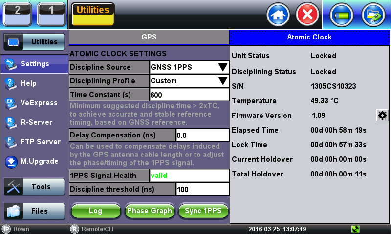
Clock Disciplining - Using the built-in GNSS 1PPS
-
With the GNSS module already locked, go to >Utilities >Settings >More >High Precision Clock >Atomic Clock.
-
Set Discipline Source = GNSS 1PPS, to use the traceable (UTC aligned) 1PPS timing signal from the GNSS receiver.
Discipline Source
-
Verify that 1PPS Signal Health = Valid, to confirm that the one-pulse-per-second signal is being detected.
-
Set Discipline Profile = Custom.
-
Set Time Constant (s) = 60 (this small window is only used to expedite the initial phase alignment process).
-
Set Discipline Threshold (ns) = 100 (a more stringent 50ns could also be tried, if applicable. Use the Phase Graph to determine the stability range).
-
Verify that Disciplining Status = Acquiring. This indicates that the disciplining process is in progress.
-
Tap on the Phase Graph to monitor the relative phase error until it becomes a horizontal line close to 0ns. The time required for this may vary (it should take less than 15 minutes)
-
Close the Phase Graph and set the Time Constant (s) = 900. You can also experiment with larger time constants (e.g. 1800s, 3600s, 5400s). The larger the constant the more stringent the disciplining process becomes and the longer it takes to achieve disciplining lock. To declare lock, the Atomic Clock verifies that the relative phase stays within the defined Disciplining Threshold for about 2x Time Constant (to confirm its stability). You can use the Phase Graph to monitor the actual phase variations on your current GNSS environment for the past 600s.
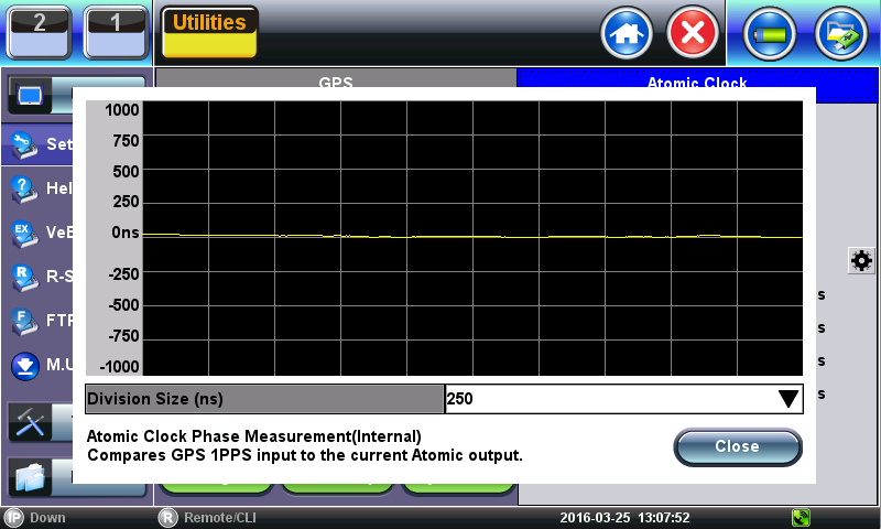
Discipline Source Phase Measurement
-
Open the Phase Graph again to monitor the time error. Once it stabilizes again around 0ns, wait for about 60 minutes. The line should stay flat and very close to 0ns. If not stable, please check the GPS satellites and antenna installation.

Discipline Source Phase Measurement
-
Close the Phase Graph and verify that the Disciplining Status gets into Locked mode.
At this point the test set’s internal “Atomic 10MHz” frequency and “Atomic 1PPS” timing reference signals can be considered accurate and stable.
The Phase Graph (above) can be used to monitor the short-term stability of the raw GPS clock, which can be used to determine the Discipline Threshold for a particular site or scenario. Zoom in to the 50ns grid and estimate how disperse the 1PPS samples are (in ns), then use a larger value as a threshold. A vertical variation of <30ns is OK.
Verifying the Antenna Field of View
Not many of us would be tempted to get on the roof or climb to the top of a tower to perform a 360° visual inspection to identify any potential satellite signal obstructions. But even if you do, you won’t be able to “see” interference, multi-path or other RF effects.
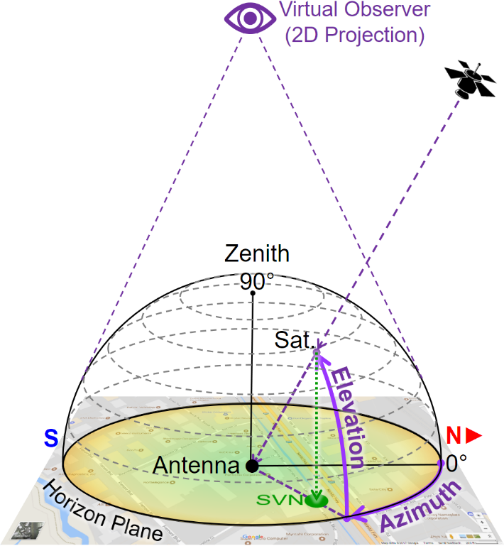
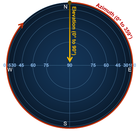
As all “visible” GNSS satellites move around their orbits, the directional vectors pointing at them form dome above the antenna. Their received signal qualities change over time, depending on their elevation angles, obstructions, reflections and other factors.
To track this, you need a tool that records the C/No of every satellite as they pass by the antenna’s aperture (field of view), to create a flat (2D) projection of a 360° color-coded dome-shaped “heat” map representing the field of view of the antenna and the signal quality from every direction. These azimuthal graphs allow you to identify areas (directions) with degraded signal quality.
Building such maps usually takes >24 hours, to allow each satellite to complete one cycle over the antenna (not to be confused with their ~12-hour orbital cycles).
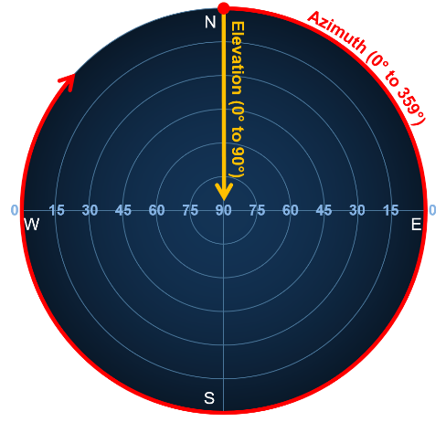
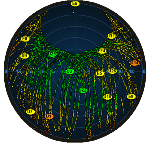
Examples of 2D Linear and Cosine projection (polar) grids, as well as actual satellite trails recorded
This type of tool can also be used to evaluate and benchmark different antennas in real life and under the same conditions. The areas in yellow indicate the directions with degraded satellite signals are, such as RF “shadows” cast bet trees and buildings. They can also indicate interference. As the signal degrade even more they turn orange and red. The example below shows the correlation between the sky view map and a map of the area around the antenna.
-
Go to >Utilities >Settings >More >High Precision Clock.
-
Turn the GNSS Receiver = OFF and close the screen.
GNSS Receiver Off
-
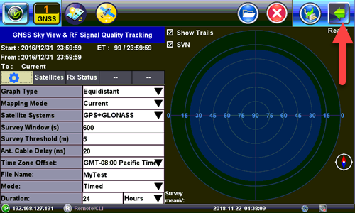
Go to >Tools>Advanced>More>GNSS.
-
Select the Time Zone from the Time Zone Offset: drop-down list box.
-
Enter a Test Name from the File Name: drop-down list box.
-
Select the Duration of the test from the Duration: drop-down list box.
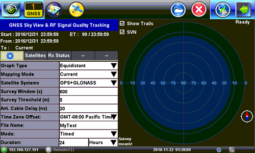
GNSS Setup
-
Tap on the Arrow to open the menu and tap on Start.
GNSS Start Menu
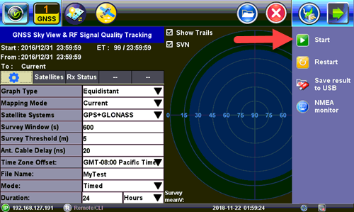
GNSS Start
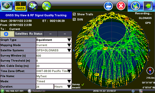
GNSS Results
-
To save Results to USB tap on the Arrow and then tap on Save Results To USB.
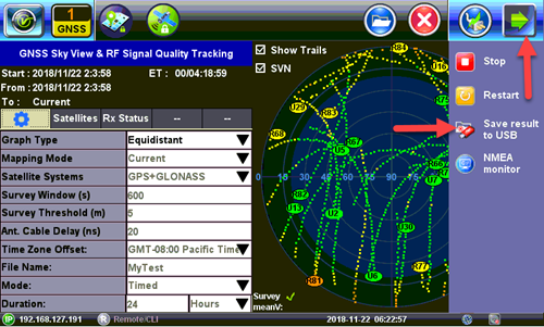
GNSS Save Results