RXT-1200 Quick Guide
The RXT® Test Platform is a family of modular telecommunication test and measurement equipment. It comprises of a common Test Platform (host or chassis) and different interchangeable test modules (each geared toward specific applications and/or technologies).
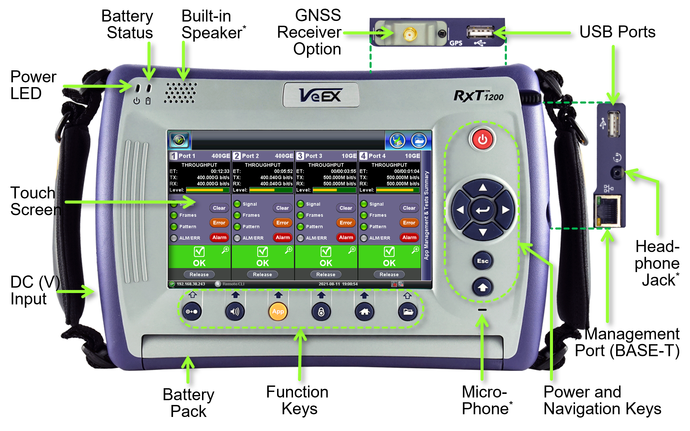
![]() Some versions of the RXT-12xx platform may not offer microphone, speaker or headset jack (optional). However, some of the features requiring audio access may still be supported by dedicated audio jacks on the test module's connector panel.
Some versions of the RXT-12xx platform may not offer microphone, speaker or headset jack (optional). However, some of the features requiring audio access may still be supported by dedicated audio jacks on the test module's connector panel.
Accessories & Hardware Options
-
One AC/DC Adapter and Power Cord
-
Optional carrying case (if ordered)
-
Optional USB WiFi 802.11a/b/g/n/ac dual-band dongle (if ordered)
-
Optional USB WiFi 802.11b/g/n + Bluetooth 4.0 dongle (if ordered)
-
Optional USB Bluetooth dongle (if ordered)
-
Optional Optical Transceivers (if ordered from VeEX)
-
Optional GNSS or Multiband GNSS receiver (comes pre-installed, if ordered)
-
Optional GPS or Multiband GNSS antenna (if ordered)
-
Optional Atomic Clock hardware option (built-in, not visible from the outside)
RXT Test Modules
The RXT-3400 multi-service test module for the versatile RXT® test platform offers state-of-the-art support for Access, Metro, Core, Transport, Carrier Ethernet, Backhaul, Fronthaul and SAN technologies up to 16GFC. VeEX RXT® is the industry’s most flexible, compact, complete and future-proof hand-held test solution, from 64k to 400GE, including Fiber Optics and WDM.
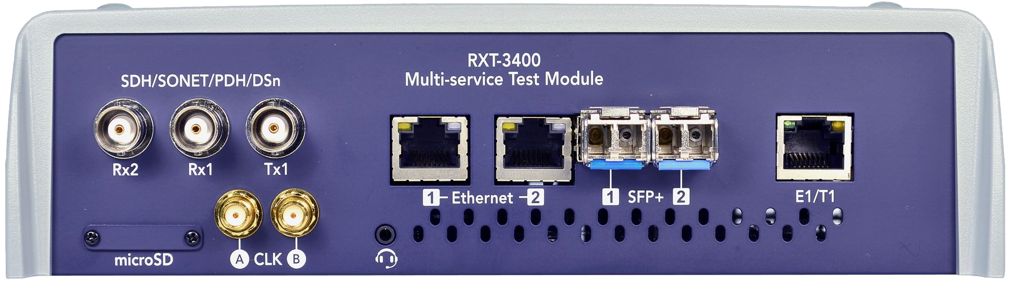
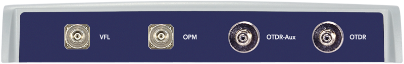
Features a range of Optical test functions including OTDR, OPM, Light Source and VFL. Physical link for OTN, SDH/SONET, Ethernet, Fibre Channel and Synchronous Packet Networks utilizing optical fibers can easily be verified as well as OSA testing on CWDM/DWDM network with a single test platform ensuring maximum test productivity.
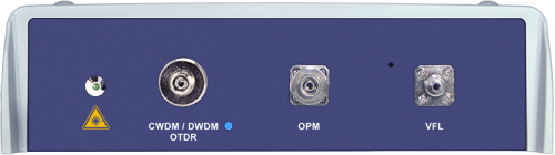
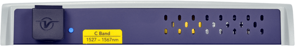
The industry’s first combined CWDM/DWDM OTDR in a single test module. CWDM and DWDM (C-band) wavelength tuning with up to 500,000 data point sampling resolution offers unprecedented network characterization.
The RXT-4500/4510 OSA modules are practical Optical Spectrum/Channel Analyzers for CWDM and DWDM networks. Using superior micro-optic design and MEMS tuning technology, the modules measure key optical parameters such as wavelength, channel power, and OSNR.
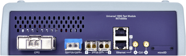
The RXT-6000e is a complete and flexible portable 100G test set. Equipped with most common transceiver form-factor ports and optional legacy test interfaces, this module is a perfect complement to the RXT® Platform, extending its testing range to 100 Gbps, with CFP2 or QSFP28 transceivers. It features OTL/PCS, CAUI-4/XLAUI Lane BERT, overhead monitor/control, Tandem Connection Monitoring, Service Disruption, Protocol Capture/Decode, BERT, Throughput test, and much more.
VeEX® RXT is the industry’s most flexible, compact, and future- proof hand-held test solution for core, metro, edge, and access networks. The RXT-6200 module adds Ethernet, 5G/4G Mobile Backhaul and Fronthaul, Storage Area Networks, OTN, as well as legacy SDH/SONET, PDH/T-Carrier links and services testing, from 1.5/2 Mbps up to 100 Gbps.
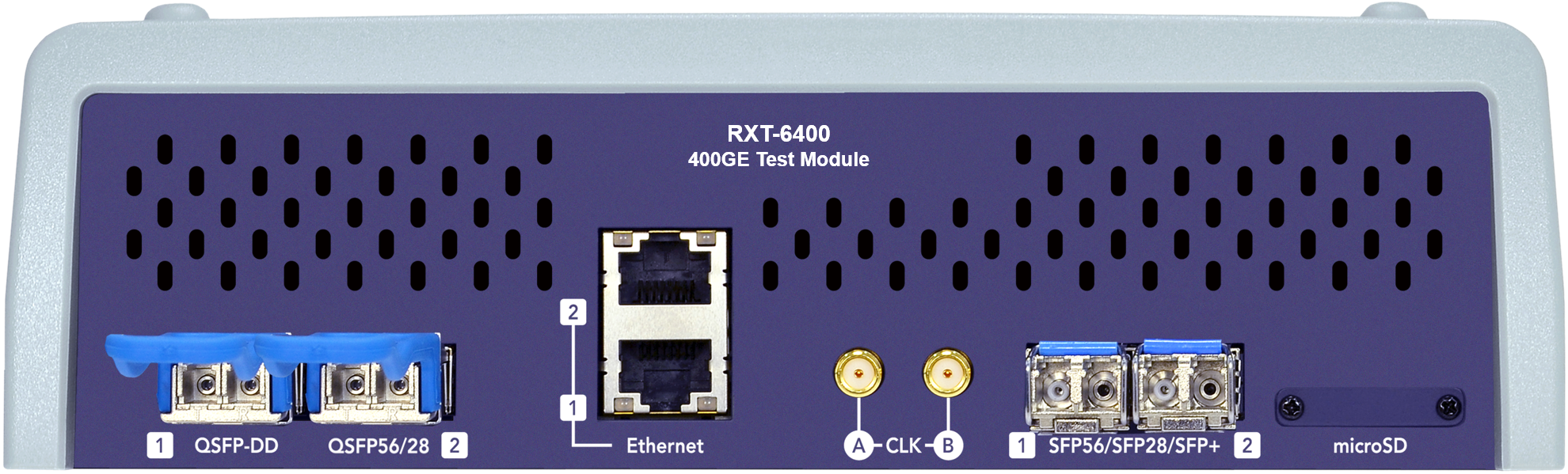
The RXT-6400 was introduced as the first truly portable 400G test set supporting native PAM4 QSFP-DD and OSFP. Equipped to support all common transceiver form-factors, this module is a perfect complement to the RXT Platform, extending its testing range to 400 Gbps and offering all-in-one 1GE-to-400GE testing capabilities. It features an array of advanced layer 1-to-4 features, such as FEC codeword Error distribution analysis, PAM4 pre-emphasis, skew, transceiver check and stress, Lane BERT, Throughput test, IPv4/IPv6, transceiver testing and much more.
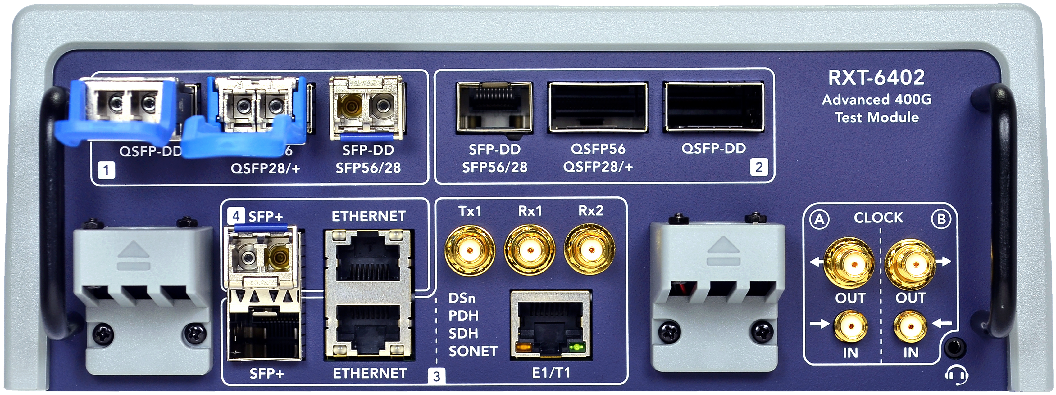
The RXT-6402 Dual 400G Multi-Service test module offers the flexibility of testing current interfaces and supporting future expandability for applications including Transport, Metro, Edge, Aggregation, cross-connect, 5G x-haul, and NEMs field support.
Basic Operations

Software Upgrades
To perform an RXT-1200™ platform (system) software upgrade, insert a FAT32 USB memory stick, with the installer package, into one of the test set's USB ports and simultaneously press the Alternate Function, Enter, and Power buttons, until it beeps.

Platform and Module software upgrades can also be performed by pointing any standard web browser to the test set's IP address and selecting Platform Upgrade and Module Upgrade from the menu. The software upgrade packages can be downloaded from www.veexinc.com, or using the test set’s built-in VeExpress client software.
Module Upgrades
To upgrade module software, insert a FAT32 USB memory stick, with the installer package, into one of the test set's USB ports. Then, attach the DC charger to the test set, power it on and go to Utilities>M.Upgrade. Once the upgrade image is recognized, confirm the versions and tap on the Upgrade button.
|
|
Turning the Test Set ON and OFF
-
Turn ON: Press and hold the red Power button for two seconds, until a confirmation tone is heard, and the power LED turns green (in noisy environments, refer to the power LED).
-
Turn OFF: Press and hold the red Power button for about two seconds, until two confirmation tones are heard. Then the shutdown process will start.
-
Forced Shut Down: In the rare case of a malfunction, our Customer Support team may instruct to press and hold the Power button for approximately four seconds, until the screen turns off. Results, data or configurations are not saved.
Power LED
A single LED indicates the power state of the unit.
-
OFF : The LED is off when the unit is powered off
-
GREEN: The LED is green when the unit is powered on and fully charged.
-
ORANGE: The AC/DC adapter is plugged in and the battery is charging.
Audible Beeps
Low Battery status is indicated by a periodic beeping sound, every four seconds, and displaying a warning pop-up message on the screen.
When working on battery power, once the charge capacity reaches about 10%, the test set will start beeping to notify users to plug in the AC/DC adapter. A pop-up message may also be presented on the screen. When the charge level reaches 5%, the test set automatically initiates the shutdown process, to protect the battery.
To get information about the amount of battery charge and autonomy estimate (under current usage condition) tap the battery icon displayed on the top-right corner of the screen.
DC Power Jacks
Depending on the test modules ordered, users receive one of the following three RXT test platform models. They are very similar, with just a few differences, such as their power capacity, DC port types, and required AC/DC adapter (non-interchangeable).

|
Forcing it in any other orientation would trigger its protection circuit and disable it for several minutes (in some cases could cause permanent damage). If it happens by accident, disconnect the DC plug from the test set and wait for about one hour before trying again.
|
 Attention: For the RXT-1202, the flat part of the DC plug must be facing towards the front of the test set (as shown in the diagram), before plugging it in. Refer to the diagram embossed on the connector cover and the label on the power cord.
Inserting and Removing Test Modules
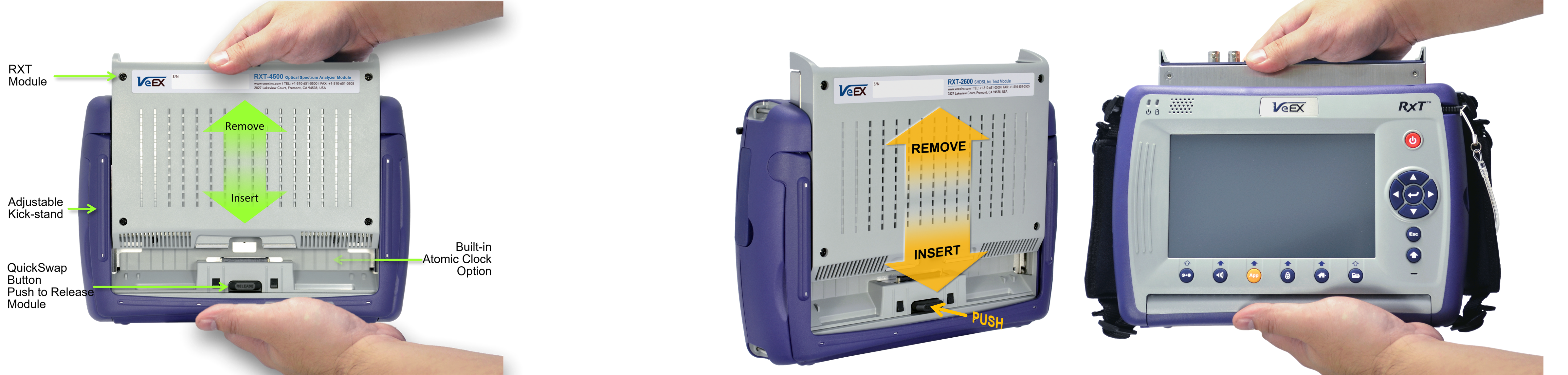
Turn the test set OFF.
-
Remove: Press the black RELEASE button on the back and pull the module out.
-
Insert: Align the module with the metal guides and push it slowly until you hear the locking "click".
If adding a new module, download the test module's software from its web page and install it using the M.Upgrade function, before using it. To find the Release Notes, go to the Resources tab of the module page on www.veexinc.com.
Identifying Test Ports and Port Groups
On the module's connector panel, test ports are identified by group numbers in white rounded squares. In multi-port test modules, each group can run one independent test. These groups may also be referred as P1, P2, P3, P4, etc.
Consider the test port groups as 'Test Resources' or 'Test heads'. Each one can run one test.
RXT-6200 Test Port Groups

RXT-6400 Test Port Groups

RXT-6402 Test Port Groups

Selecting the Test Port Group
-
Identify the type of interface being used by the link or device to be tested.
-
On the test module, identify a test port group with an available port or transceiver type that matches the link or device under test. (Note: If you need to use a QSFP28 transceiver for 100GE, but Group 1 is already running a 25GE test with SFP28, even if the P1 QSFP28 slot is available, it can't be used. Then you must select a port from Group 2. Each group can only run one test.)
-
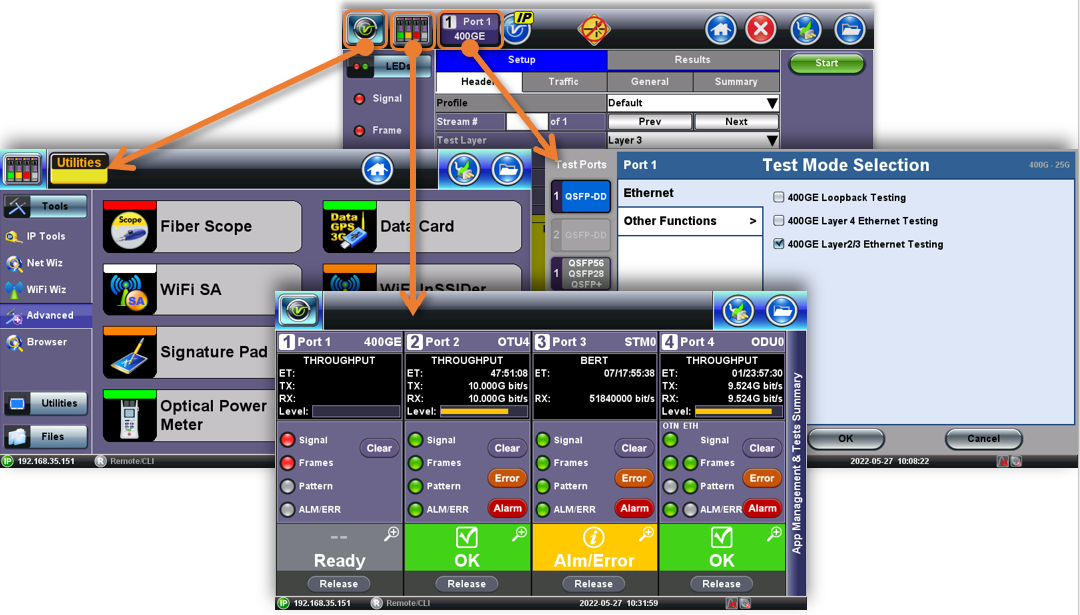
From the GUI, select the test port group. Depending on the test module type, number of supported concurrent tests, and software version, tap on:
-
One of the available Test Port Group buttons, 1 or 2, on the top-left corner of the screen. (If a Port Group is already being used, it will display the test type on the bottom-half of the button, with either yellow/idle, green/good or red/alarm background color indication.)
-

--OR--
The New button on one of the available Test Cards, according to the test interface required for the application. Depending on each individual test module and/or hardware configuration, the screen may display two, three or four test cards.

The test set will display the Test Mode Selection menu.
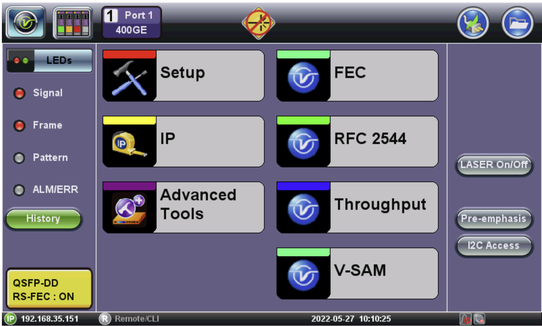
Test Modes - Launching Test Applications

From the Test Mode Selection menu, select the:
-
Test port, using the buttons on the left. (The available selection will change based on the capabilities of the selected port group.)
-
Protocol (technology or link type), using the vertical tabs. (The available selection will depend on the capabilities of the selected port type.)
-
Test Application, using the check boxes. (The available test functions will depend on the of the selected protocol and purchased licenses.)
-
Press OK to launch the Test Application.
The selected test application will start to launch (it may take several seconds).
Insert the required optical transceiver (if applicable) and connect the selected test port to the Fiber, Link, Line Card and/or Device Under Test (DUT), to set up the test scenario and start testing.
Use the buttons on the left of the top bar to navigate between the different functions (System Tools/Utilities, Test Card Summary/Test Selector, Current Test/Change Test Mode).
![]() Refer to the individual test module and test function manual for more details on the application.
Refer to the individual test module and test function manual for more details on the application.
Remote Access & Control
When connected to a network, the platform's management IP address (from LAN, WiFi or Cellular Modem) is displayed on the bottom-left corner of the screen. Users on the same LAN environment (or through VPN) can type the IP address on a browser's URL field, to gain remote access to the test set.
Other Features
![]() or
or ![]() Tap to access to the test platform (system) related settings, test results, utilities and certain tools (Fiber Scope, OTDR Viewer), including connectivity (LAN, WiFi, Bluetooth) and cloud-related applications like EZ-Remote, VeExpress, FTP, R-Server, etc.
Tap to access to the test platform (system) related settings, test results, utilities and certain tools (Fiber Scope, OTDR Viewer), including connectivity (LAN, WiFi, Bluetooth) and cloud-related applications like EZ-Remote, VeExpress, FTP, R-Server, etc.
Test Cards Summary / Application Switching
![]() Tap to access the Test Cards Summary, which shows an overview of all active tests and test resource availability. Test applications can be terminated/released or new ones can be assigned.
Tap to access the Test Cards Summary, which shows an overview of all active tests and test resource availability. Test applications can be terminated/released or new ones can be assigned.
Active Test Application
![]() This button indicates the current Port (1) on Module (2) is being currently presented on the screen. Tap this button to change the Test Mode or Test Application for this port.
This button indicates the current Port (1) on Module (2) is being currently presented on the screen. Tap this button to change the Test Mode or Test Application for this port.