Capture Images (View)
The Capture tab is the main user interface for the connector end face inspection and analysis. It presents a real-time view of the connector’s end face allowing for alignment and focus. The capture screen displays a live image of the connector face and features analysis and freeze tools.
The fiber end face image will normally display near the middle of viewing window area. The exception will be when inspecting bulkhead/couplers of APC connectors or using A6 type tips. The end face image will appear off-center. AutoFocus and Shake OFF setting is recommended when inspecting couplers. Gently adjust centering while manually focusing the image and image will freeze as soon as focus is achieved.
For the DI-3000, press the autofocus (red target) button when the image is out of focus to enable the device's automated focusing operation. With a steady hand, the end face will be promptly autofocused and ready for capture.
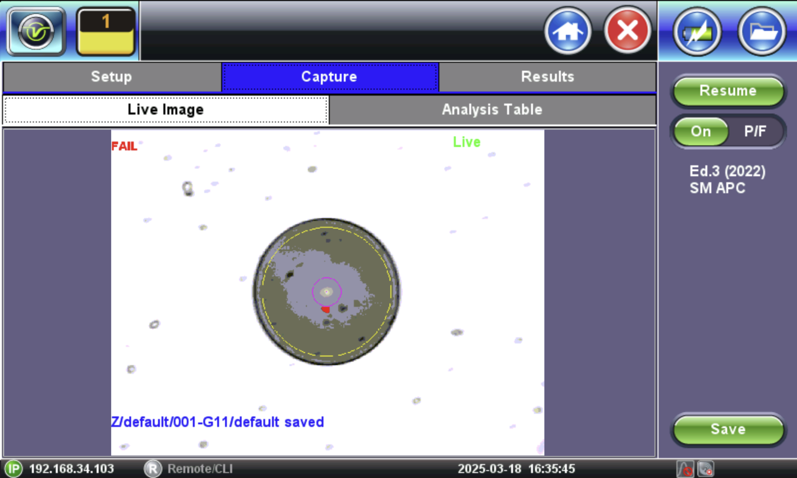
Real time video of the connector face. Red contours indicate scratches and defects.
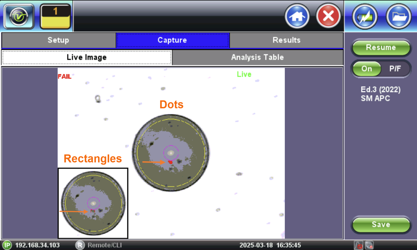
Fiber Scope Capture - Dots vs Rectangles
-
Resume / Freeze: Stops the video capture from the fiberscope. If the optional Auto Freeze feature is enabled, the test set will automatically freeze the image when it comes into focus. Once the image is frozen, tap the image to save it.
-
On / OFF: Turn ON/OFF the automatic Pass/Fail threshold defined by IEC 61300-3-35.
To save the image on the screen, tap the screen after freezing or Save.
After saving, go to Results to push to the cloud. To view the Test Report, go to ![]() > Utilities > Files
> Utilities > Files
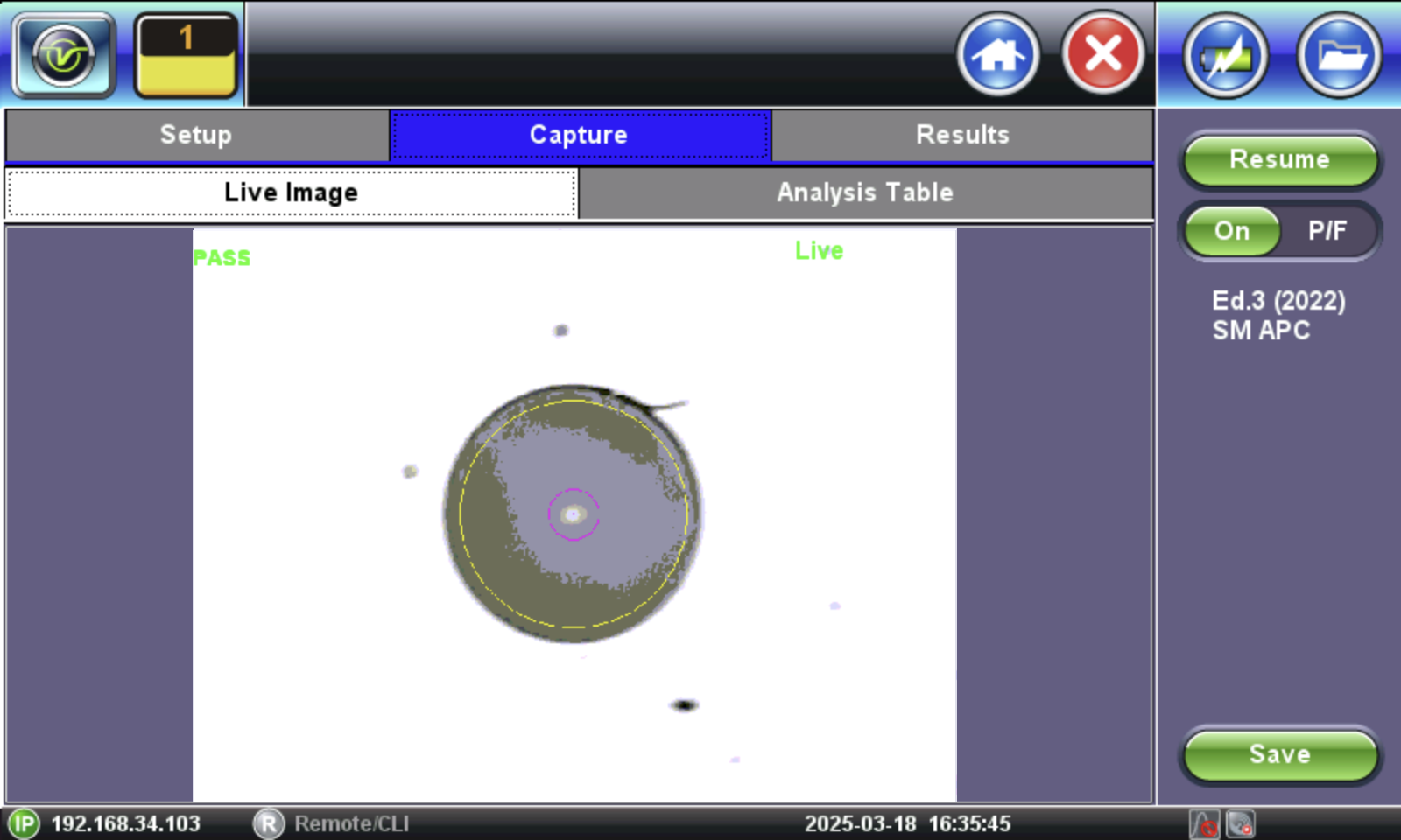
Fiber Scope Capture - PASS
When "Tap screen to save" appears on the image, it indicates that the Autosave on Tap option was enabled on the Setup tab. If Autosave after freeze were selected, the "Tap screen to save message" would not appear.
![]() This table will also be included in the reports.
This table will also be included in the reports.
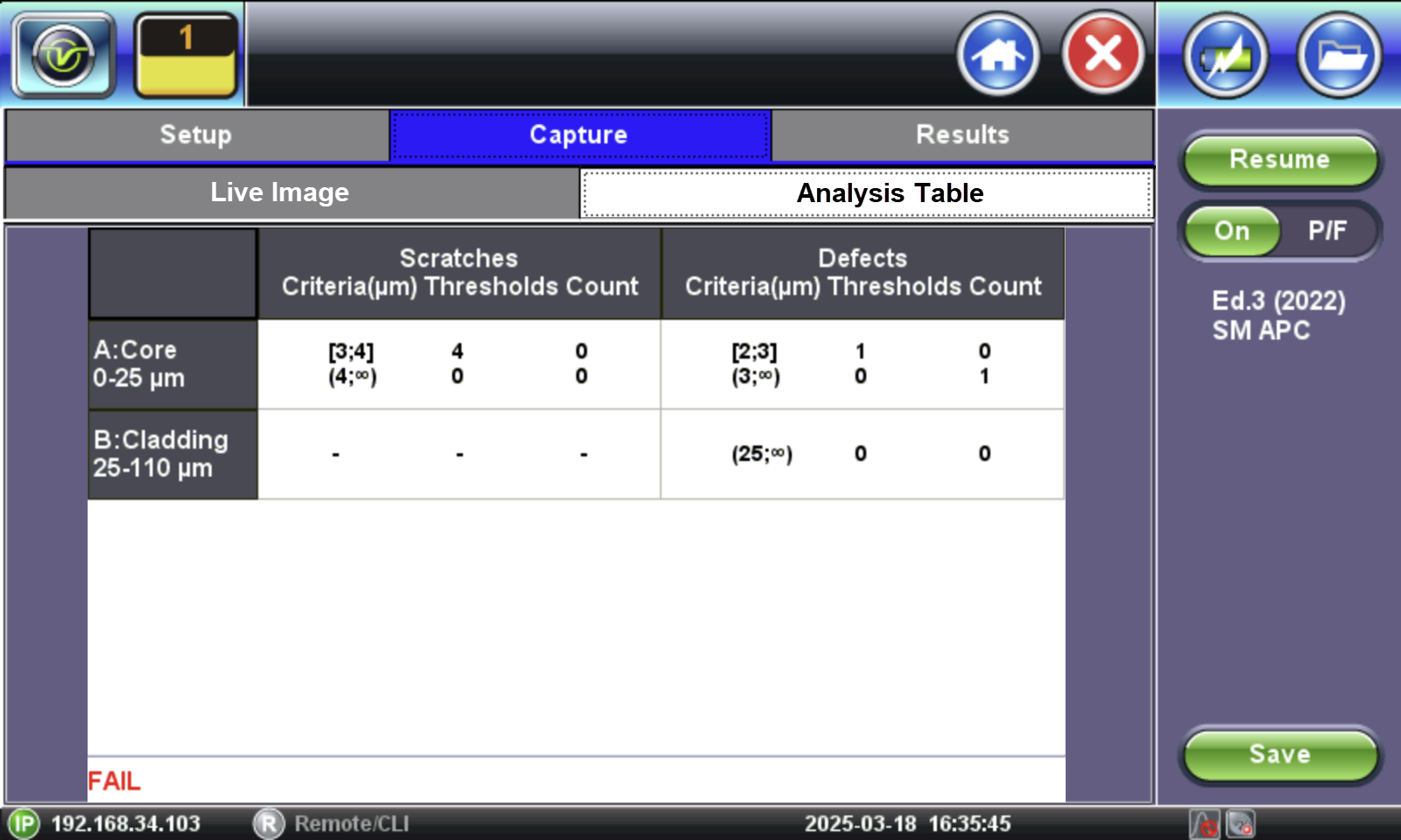
Pass/Fail IEC analysis table
(Measured scratches and defects compared with threshold criteria for each fiber layer)