BERT/Throughput
Overview
The test set complies with ANSI NCITS FC-FS recommendations and has the ability to test 1, 2, 4, 8 and 10 Gigabit Fibre Channel.
- 1/2/4/8G Fiber Channel: The unit verifies the 8B/10B PCS Layer with a basic primitive set at FC-1 or FC-2 lower layers.
- 10G Fiber Channel: The unit verifies the 64B/66B PCS Layer with a basic primitive set at FC-1 or FC-2 lower layers.
- FC-1 Layer addresses the transmission protocol encoding, decoding, and special characters used for protocol management
-
FC-2 is the signaling protocol layer, which is made up of a framing protocol and a flow control process +
The unit supports the generation and monitoring of: bit errors, order sets, frame delimiters, frame transmission, and generation of primitive sequences. BERT diagnostics perform a bit-by-bit comparison to find bit errors in the received data pattern. Error Count and Error Rate for the latest sample are displayed and maintained, as well as totals for all samples from the test start.
The user can use a default frame header or define a custom frame header - the unit takes care of the frame/header setup, creates the user defined SOF and EOF delimiters and calculates the CRC error checking bytes, which are placed within the frame. User defined bytes, fixed patterns or industry standard PRBS patterns can be selected from drop-down menus and radio buttons and inserted into the payload field.
Testing is supplemented with the capability to perform Bit and CRC error insertion. These tests allow users to test their own Mux demux equipment for error monitoring and detection. The test set displays the BERT test results continuously and any anomaly is recorded in an event log which is date and time stamped. All results can be saved and exported into ReVeal MX for analysis or customer test report generation.
Fiber Channel Layers
The Open Systems Interconnect (OSI) model breaks communications into seven layers namely, Physical, Data Link, Network, Transport, Session, Presentation, and Application. Fibre Channel does not follow the ISO model - instead, the protocol has been broken into five layers: FC-0, FC-1, FC-2, FC-3, and FC-4.
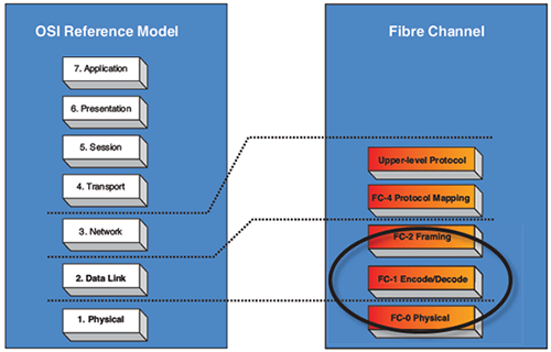
OSI layers versus FC layers
- FC-0 defines the physical portions of Fibre Channel, including the media types, connectors, and the electrical and optical characteristics needed to connect ports. This level is in the FC-PH standard.
- Signaling
- Media specifications
- Receiver/Transmitter specifications
- FC-1 defines the transmission protocol, encoding, order of word transmission, and error detection. This level is in the FC-PH standard.
- 8B/10B character encoding (1/2/4/8G FC) or 64/66B character encoding (10G FC)
- Link maintenance
- FC-2 defines the signaling and framing protocol, including frame layout, frame header content, and rules for use. It also contains independent protocols such as login. This is the bulk of the FC-PH standard.
- Frame format
- Sequence management
- Exchange management
- Flow Control
- Classes of Service
- Login/Logout
- Topologies
- Segmentation and Reassembly
Fiber Channel layers and functionality
| OSI Model | Fiber Channel | Description |
| Layer 2: Data link |
FC-2 | Similar to the MAC functionality - Fiber Channel frames are defined, addressed and CRC are added. |
| Layer 1: Physical |
FC-1 FC-0 |
Similar to the physical layer of the OSI model - Fiber Channel adds basic flow control functionality and ordered sets. |
- FC-3 defines common services that may be available across multiple ports in a node. This level has no standard now.
- Services for multiple ports on one node
- FC-4 defines the mapping between the lower levels of Fibre Channel, and the command sets that use Fibre Channel.
- Upper Layer Protocol (ULP) mapping
- Small Computer System Interface (SCSI)
- Internet Protocol (IP)
- High Performance Parallel Interface (HIPPI)
- Asynchronous Transfer Mode - Adaption Layer 5 (ATM-AAL5)
- Intelligent Peripheral Interface - 3 (IPI-3) (disk and tape)
- Single Byte Command Code Sets (SBCCS)
- Upper Layer Protocol (ULP) mapping