Setup
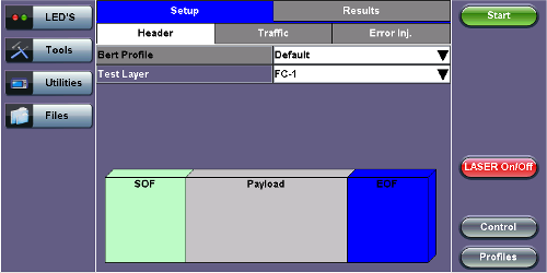
FC-1 BERT - Test Frame Setup
-
Profile: User Defined Profile or Default setting can be used for testing.
-
Test layer: FC-1 or FC-2 only. Testing at other layers is not supported.
-
FC-1:Information is transmitted using an adaptive code (8B/10B or 64/66B) depending on test rate and the encoding process results in the generation of transmission characters.
The two types of Transmission Characters defined are data and special. Certain combinations of Transmission Characters, referred to as Ordered Sets, are designated by this standard to have special meaning.
Ordered Sets are used to identify frame boundaries, transmit primitive function requests, and maintain proper link transmission characteristics during periods of inactivity.
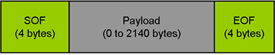
FC-1 Frame Structure
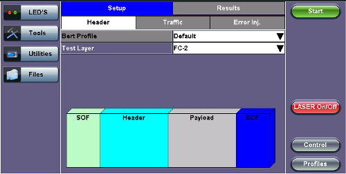
FC-2 BERT - Header Setup
- FC-2: Only FC-2 frames have a header, so these fields are not available for FC-1 frames.
- Defines the framing rules and mechanisms for controlling the different service classes. The following building blocks are defined by the standard:
- Ordered Set
- Frame
- Sequence
- Exchange
- Protocol
- Defines the framing rules and mechanisms for controlling the different service classes. The following building blocks are defined by the standard:
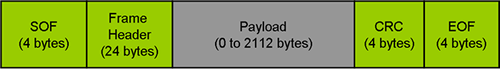
FC-2 Frame Structure
![]() FC-2 Header
FC-2 Header
The FC-2 header is only 24 bytes long. Header settings do not affect the transmission or reception of the FC-2 frame.
Understanding the Basic Test Channel Frame Structure
The Fibre Channel standard defines a variable frame length consisting of 36 bytes of overhead and up to 2112 bytes of payload for a total maximum size of 2148 bytes.
- SOF and EOF
- A Start of Frame (SOF) delimiter and End of Frame (EOF) delimiter mark the beginning and end of each Fibre Channel frame
- Available for both FC-1 and FC-2 frame formats
- Frame Header
- Is the first field of the frame content and immediately follows the SOF delimiter and is transmitted on a word boundary
- Is used to control link operations and device protocol transfers as well as detect missing or out of order frames
- Available in FC-2 frame format only
- CRC - The Cyclic Redundancy Check (CRC)
- Is a four byte field that follows the Data Field and is used to verify the data integrity of the Frame Header and Data Field.
- SOF and EOF delimiters are not included in the CRC verification
- The CRC field is calculated on the Frame Header and Data Field prior to encoding for transmission and after decoding upon reception
Frame Delimiters
A frame delimiter is an Ordered Set that immediately precedes or follows the contents of a frame. Separate and distinct delimiters shall identify the start of a frame and the end of a frame and shall be recognized when a single Ordered Set is detected. An Ordered set is described below.
Ordered Set
An Ordered Set is a four-character combination of data and special Transmission Characters. Ordered Sets provide the ability to obtain bit and word synchronization that also establishes word boundary alignment. The three types of Ordered Sets are:
- Frame Delimiters
- (SOF) Start-of-Frame
- (EOF) End-of-Frame
- Primitive Signals
A Primitive Signal is an Ordered Set designated to have special meaning. All FC_Ports shall at a minimum recognize R_RDY and IDLE Primitive Signals. All Primitive Signals not recognized by the FC_Port shall be treated as an IDLE.- Idle: Idle is a Primitive Signal transmitted on the link to indicate that link initialization is complete and to maintain link synchronization
- (R_RDY) Receiver Ready
- Primitive Sequence
- (OLS) Off-line
- (NOS) Not Operational
- (LR) Link Reset
- (LRR) Link Reset Response
Start of Frame (SOF) and End of Frame (EOF) Delimiter setup
The Start-of-Frame (SOF) delimiter is an Ordered Set that immediately precedes the frame content. There are multiple SOF delimiters defined for Sequence control. SOF indicates that a Frame will immediately follow and indicates which class of service the Frame will use.
The value of the SOF field determines the class of service associated with the FC frame. Several Classes of service are specified in Fiber Channel but only Classes 1,2,3 & 4 are described below. Classes 1, 2, and 3 are topology independent, however, Classes 4 and 6 require a Fabric. If the Fabric is not present, the service is provided as a special case of point-to-point. FC_Ports are not required to support all classes of service.
- Class 1: Dedicated physical connection with delivery confirmation. This class of service has three phases:
- Setting up the connection
- Transferring the information
- Closing down the connection
- Class 2: Frame multiplexed service with delivery confirmation. No dedicated connection between the two communication parties is established. This class of service allows a stream of frames to be sent to different destinations quickly. Class 2 also requires frame confirmations by the recipient.
- Class 3: Is sometimes called "datagram". It is "connectionless" service with the Fabric multiplexing frames at frame boundaries, if a Fabric is present. If a Fabric is not present, this service becomes a special case of point-to point.
- Class 4: Is a service that uses a virtual circuit established within a Fabric and between two communicating Nx_Ports to transmit frames to each other using a fabric-managed fractional bandwidth allocation protocol. This service requires a Fabric.
The following SOF Service Class selections are available:
- SOF Initiate (SOFix)
A Sequence shall be initiated and identified by using SOFi1, SOFi2, SOFi3, or SOFi4 in the first frame. SOFix is used to represent these four SOF delimiters.- SOF_i3: Contains a code value of 0x2E indicating SOF Initiate Class 3. A SOFi3 should be used on the first frame of a Sequence for Class 3 Service.
- SOF Normal (SOFnx)
The following delimiters identify the start of all frames other than the first frame of a Sequence based on class of service. SOFnx is used to indicate SOFn1, SOFn2, SOFn3 and SOFn4.- SOF_n3: Contains a code value of 0x36 indicating SOF Normal Class 3. The SOFn3 shall be used for all frames except the first frame of a Sequence for Class 3 Service.
- SOF Fabric (SOFf)
- SOF_f: Contains a code value of 0x28 indicating SOF Fabric. If an Nx_Port or Fx_Port receives a Class F frame, indicated by an SOFf delimiter, it shall be discarded by the Nx_Port or Fx_Port. The receiving Nx_Port or Fx_Port may send an R_RDY
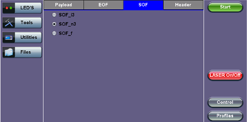
FC-2 BERT - SOF Setup
End of Frame (EOF)
The End-of-Frame (EOF) delimiter is an Ordered Set that immediately follows the CRC and is transmitted on a word boundary. The EOF delimiter designates the end of the frame content and is followed by Idles. There are three categories of EOF delimiters found in the Fiber Channel standard, however the test set only supports the first category that indicates that the frame is valid from the sender's perspective and potentially valid from the receiver's perspective.
The following selections are available:
- EOF_t: Contains a code value of 0x42 indicating EOF Terminate. The EOFt indicates that the Sequence associated with this SEQ_ID is complete. EOFt is used to properly close a Sequence without error.
- EOF_n: Contains a code value of 0x41 indicating EOF Normal. The EOFn identifies the end of frame when one of the other EOF delimiters indicating valid frame content is not required.
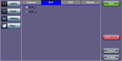
FC-2 BERT - EOF Setup
Payload
The test set implements and observes "Methodologies for Jitter and Signal Quality Specification (MJSQ)". A major goal of MJSQ is to improve the relationship between measurements on signals and receiver performance in terms of bit errors. The unit transmits a "compliant pattern" which consists of a valid Fiber Channel protocol frame (SOF, payload, CRC, EOF) containing a test pattern as the payload. Different payload selections are available depending on the Fiber Channel layer to be tested. The payload consists of 0 to 2112 bytes, and is sent in 4 byte increments, otherwise it is considered to be a misaligned frame.
FC-1 Payload (test pattern)
Layer 1 test patterns are formatted using the 8B/10B symbol format and include the PCS layer as part of the BER pattern.
CRPAT, CSPAT, and CJTPAT test patterns according to NCITS-TR-25-1999 and MJSQ, are designed to evaluate frequency fluctuations, transceiver noise and phase jumps caused by jitter and other anomalies. These test patterns are described briefly as follows:
- CSPAT: Compliant Supply Noise Pattern
- Represents worst case power supply noise
- CRPAT: Compliant Random Pattern
- Provides broad spectral content and minimal peaking for the measurement of jitter at component or system level
- CJTPAT: Compliant Jitter Test Pattern
- Jitter Tolerance Pattern that stresses a receiver by exposing it to extreme phase jumps thereby stressing the clock data recovery (CDR) circuitry
- The pattern alternates between repeating low transition density patterns and repeating high transition density patterns
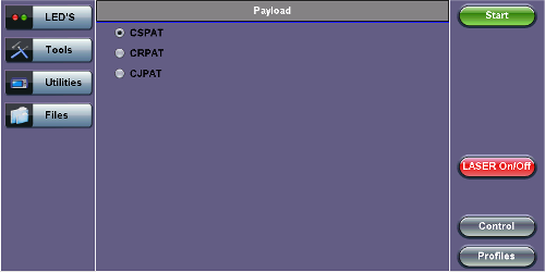
FC-1 BERT - Payload Setup
![]() FC-1 Test Patterns
FC-1 Test Patterns
CRPAT sequence is offered for TX jitter measurements.
CRPAT and CJTPAT are available for RX jitter tolerance measurements - use these test patterns to test the resilience of the receiver (Clock Data Recovery - CDR) and its tolerance to signals with jitter.
FC-2 Payload (test patterns)
Layer 2 "Compliant" test patterns are modified to resemble a true Fiber Channel frame - the pattern's format is similar to a basic frame which includes a Start of Frame Delimiter (SFD), End of Frame Delimiter (EFD), and Cyclic Redundancy Check (CRC).
Pseudo Random Bit Sequences (PRBS) are commonly used to test the signal integrity of high-speed links and are defined in ITU-T 0.150 & 0.151 Recommendations – These legacy SONET/SDH/PDH test sequences may appear random but they have specific properties that can be used to measure the quality of a link. PRBS patterns can be normal or can be inverted.
- 2E31-1: 147 483 647-bit pattern used for special measurement tasks, (e.g., delay measurements at higher bit rates)
- 2E23-1: 8 388 607 bit pattern primarily intended for error and jitter measurements at bit rates of 34 368 and 139 264 kbps
- 2E15-1: 32 767 bit pattern primarily intended for error and jitter measurements at bit rates of 1544, 2048, 6312, 8448, 32 064 and 44 736 kbps
- 2E11-1: 2047 bit pattern primarily intended for error and jitter measurements on circuits operating at bit rates of 64 kbps and N x 64 kbps
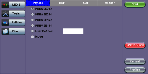
FC-2 BERT - Payload Setup
![]() BERT Testing Tips
BERT Testing Tips
A BERT samples every incoming bit and looks for something that doesn't occur often. This traditional method typically used in SONET/SDH measurements, can however take a very long time. For example, in a 1Gbps Fiber Channel system, errors occur on average once every 1000 s (about 17 Min) for 1x10–12 BER, so you would need to detect at least 10 to 100 errors before you can have confidence in your measurement. Bear in mind that for a quick measurement, you need a test pattern that repeats frequently. A PRBS-11 sequence (2047 bits) repeats many times a second at a 1-Gbps rate, however a PRBS-31 pattern, with 2 billion bits, repeats only every 2 s at 1 Gbps.
A general rule of thumb is to choose a PRBS that is closest to the nature of the data you will be passing through your network. Patterns between 211–1 and 231–1 (such as 215–1 and 223–1) offer good gradual steps in difficulty that allow you to see where networks fail, or how much margin you have beyond pass/fail thresholds.
Bit errors can affect the data frames - these frames will be re-transmitted at the request of the upper-layer protocols. If the FC link suffers a lot of bit errors, you may experience a slight performance loss. These bit errors can also affect the Receiver Ready (R_RDY) messages. A R_RDY is never repeated, so the buffer credit is one BB_Credit short until the link is reset.
The Fiber Channel standard allows a 1 x 10E-12 maximum error rate.
Header Setup (FC-2 only)
The FC-2 Frame Header is subdivided into the fields as shown in the diagram below.
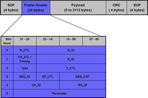
FC-2 Header Format
The Frame Header is the first field of the frame content and immediately follows the SOF delimiter. The Frame Header is used to control link operations and device protocol transfers as well as detect missing or out of order frames. The values of each field can be edited depending on network setup and test scenario. A brief description of each parameters is provided below.
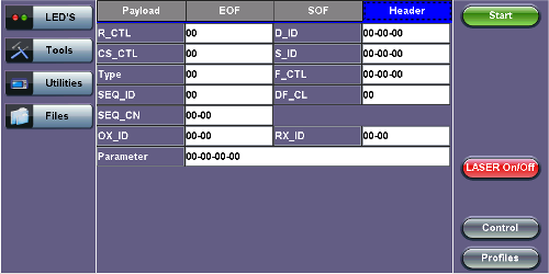
FC-2 Header Setup
- Routing Control (R_CTL):
- The R_CTL field is a one-byte field in Word 0 Bits 31-24 that contains routing bits and information bits to categorize the frame function.
- When used in combination with the TYPE field (Word 2, bits 31-24), it provides an FC_Port with assistance in frame routing, data routing, or addressing.
- The R_CTL field is further subdivided into the ROUTING field (bits 31-28) and the INFORMATION field (bits 27-24).
- D_ID Address Identifier:
- Destination Identifier is a three-byte field (Word 0, Bits 23-0) that contains the address identifier of the destination Nx_Port.
- Each Nx_Port has a native N_Port_ID that is unique within the address domain of a Fabric. It may also represent hunt groups, domain controllers, and other servers.
- Class Specific Control (CS_CTL)/Priority:
- When bit 17 of F_CTL is set to zero, Word 1, bits 31-24 of the Frame_Header is defined as the CS_CTL field.
- Contains management information for the class of service identified by the SOF. The meaning of the CS_CTL field is dependent on the class of service.
- When supported by FC_Ports, the Priority field shall be used to resolve resource contention or to determine the order to deliver frames. The definition and use of the Priority field is class dependent.
- S_ID Address Identifier:
- The S_ID is a three-byte field (Word 1, Bits 23-0) that contains the address identifier of the source Nx_Port.
- Type (Data Structure Type):
- The data structure type (TYPE) is a one-byte field (Word 2, Bits 31-24) that identifies the protocol of the frame content for Data frames.
- Frame Control (F_CTL):
- The Frame Control (F_CTL) field (Word 2, Bits 23-0) is a three-byte field that contains control information relating to the frame content such as
exchange, retransmission, or sequence control. It is also used to identify the function of the
CS_CTL/P field.
- The Frame Control (F_CTL) field (Word 2, Bits 23-0) is a three-byte field that contains control information relating to the frame content such as
exchange, retransmission, or sequence control. It is also used to identify the function of the
- Sequence Identifier (SEQ_ID):
- The SEQ_ID is a one-byte field (Word 3, Bits 31-24) assigned by the Sequence Initiator that is unique for a specific D_ID and S_ID pair while the Sequence is open.
- Both the Sequence Initiator and the Sequence Recipient track the status of frames within the Sequence using fields within the Sequence_Qualifier.
- Data Field Control (DF_CTL):
- Data Field Control (DF_CTL) is a one-byte field (Word 3, Bits 23-16) that specifies the presence of optional headers at the beginning of the Data_Field for Device_Data or Video_Data frames.
- DF_CTL bits are not meaningful on Link_Control or Basic Link Service frames.
- Sequence count (SEQ_CNT):
- The sequence count (SEQ_CNT) is a two-byte field (Word 3, Bits 15-0) that indicates the sequential order of Data frame transmission within a single Sequence or multiple consecutive Sequences for the same Exchange.
- Originator Exchange_ID (OX_ID):
- The Originator Exchange_ID is a two-byte field (Word 4, Bits 31-16) that identifies the Exchange_ID assigned by the Originator of the Exchange.
- Each Exchange is assigned an identifier unique to the Originator or Originator - Responder pair.
- Responder Exchange_ID (RX_ID):
- The Responder Exchange_ID is a two byte field (Word 4, Bits 15-0) assigned by the Responder that provides a unique, locally meaningful identifier at the Responder for an Exchange established by an Originator and identified by an OX_ID.
- Parameter:
- The Parameter field (Word 5, Bits 31-0) has meanings based on frame type.
- For Link_Control frames, the Parameter field is used to carry information specific to the individual Link_Control frame.
- For Data frames with the relative offset present bit set to 1, the Parameter field specifies relative offset, a four-byte field that contains the relative displacement of the first byte of the Payload of the frame from the base address as specified by the ULP.
For detailed information, please visit http://www.incits.org/ and download the Fiber Channel FRAMING AND SIGNALING-2 (FC-FS-2) standard.