RX Lane Skew
![]() Lane skew is only available on 100G test modules.
Lane skew is only available on 100G test modules.
Lane Skew
In OTU4 and 100GE implementations, the transmit data stream is split into 10 electrical lanes and 20 logical lanes, which are scrambled to ensure sufficient transition density (pulses) for clock recovery. The OTL/PCS layer is responsible for inserting Lane Alignment Markers into each of the logical lanes in the transmit direction, so the original 100G data stream can be reconstructed at the far end. The receiver’s OTL/PCS layer is responsible for detecting the lane alignment markers and aligning recovered data in the receive direction. The alignment process ensures properly formatted data. Skew accumulation occurs downstream from the OTL/PCS and it is the responsibility of the receiver’s OTL/PCS layer to remove skew and re-align the receive data.
Fixed Skew
Fixed or static skew represents the constant difference in arrival time for two signals generated from the same source. It is generated by physical lane-to-lane differences in the time a signal reaches a destination relative to the data on any other lane. This usually related to implementation factors, such as differences in electrical trace lengths (0.5 UI/cm), fiber optics dispersion, and lane-dependent clock recovery circuits (CDR).
Dynamic (Variable) Skew
Lane-to-lane skew can change or wander over time due to many physical and environmental factors, including uneven temperature, data rate, and supply voltage fluctuations.
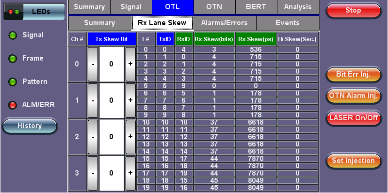
OTL Rx Lane Skew