High Precision Clock Sources
GPS/GNSS Receiver (HW Option)
The optional high-sensitivity GPS/GNSS modules (built-in) provide accurate Phase alignment and Coordinated Universal Time (UTC) synchronization to the test set, in the form of internal pulse-per-second (1PPS) clock synchronized to the standard second and timestamps. This is used to assure that two or more geographically-distributed test sets have the exact same time and can calculate delays. One example is the One-Way-Delay (Latency) tests used to identify asymmetry between each direction of a link.
The GPS Time of Day (ToD) can also be used to precisely set the local date and time in the test set, using the Sync ToD function, which will apply the local time zone correction before applying it to the test set system real time clock. This timestamp is used for reports and events, but not for time-sensitive testing.
GPS ToD is also used in One-Way-Delay (OWD) measurements and time is applied directly to each test set before the test starts, so they all have accurate time.
The GPS/GNSS receivers can be turned OFF if not used, to save battery power.
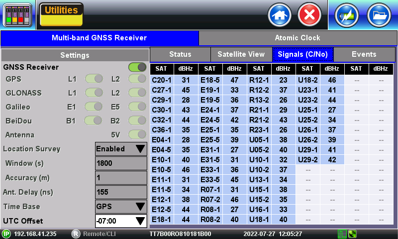
A satellite table, showing satellites in view, satellites being used and signal to noise density, is provided for information only, so the correct antenna installation can be verified. Geographical coordinates are also provided for information only and it could be used in the future to geo-tag some position-sensitive results. The GPS/GNSS antenna must have direct view to the sky. At least four satellites with SNR of 34 dB-Hz or better are recommended for accurate testing.
Atomic Clock (HW Option – Factory installed)
The optional built-in chip-scale Atomic Clock module provides a highly stable clock source to the test set, in the form of a highly accurate and stable internal 10 MHz frequency and 1PPS timing references. These references can be used to drive PDH/DSn, SDH/SONET/OTN or SyncE Master transmitters or be used as a reference for Frequency, Phase, Time Error, and Wander measurements. Their main function is to serve as a precision reference to measure wander (clock stability), even in places where there is no reference clock signals available that can be traced back to a Primary Reference Clock (PRC) or Primary Reference Time Clock (PRTC).
GPS-Disciplined Clock
When GPS/GNSS and Atomic Clock options are installed and enabled, the Atomic Clock uses the GPS signal to calibrate its frequency (10 MHz) and timing references (1PPS), to improve their accuracy and stability. The Atomic Clock 1PPS phase is disciplined to the UTC to align it with the standard second. The raising edge of the 1PPS pulse indicates the beginning of a new second all over the world.
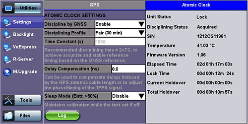
Disciplining can be disabled or enabled. When disabled, the atomic clock runs at its natural frequency (free-running), providing a very stable frequency source. When disciplining is Enabled, the atomic clock will use the GPS/GNSS accuracy to correct its frequency and align its phase.
The Disciplining Profile sets a time window the atomic clock's dynamic control loop, to filter any short term frequency and phase variations coming from the GPS/GNSS receiver, this is called Time Constant. The longer the time constant, the more accurate and stable the atomic clock output can be. The Disciplining Profile field provide suggested options for the minimum disciplining times and sets the equivalent Time Constant. The selection varies with applications and location, so some experimentation may be required by users to select their own default value. For quick field Wander or Phase measurements a disciplining time of ≥ 60 minutes (TC ≥ 1800 seconds) is recommended. Users can also enter a customized time constant in seconds.
Holdover
In case of GPS/GNSS signal loss (e.g. indoor testing) the high stability of the Atomic Clock can maintain synchronization for a few hours allowing users to perform quick Wander and Absolute Phase Error in conditions that were not possible before. This is called holdover mode.
Delay Compensation can be used to perform minor adjustments to the 1PPS phase, to align it to a specific reference or to compensate for short cable delays.
When enabled, the low power Sleep Mode keeps the atomic clock powered up when the test set is turned off. This way it maintains its last calibration by drawing little current from the batteries. In this state, the test set will only cut the power to the atomic clock if the battery charge reaches a level less than 50% of charge, to conserve battery. The Elapsed Time counts the time since its first initialization, including the time the test set has been off. If disabled, the atomic clock is shut down with the test set and will require full initialization the next time it is powered up.
Atomic Clock Relative Phase Monitoring
VeEX test sets equipped with GPS/GNSS receiver and Chip Scale Atomic Clock options include a relative phase monitoring tool that can be used for the Relative Phase Measurements that provide a bit more visibility into the disciplining process.
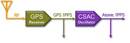
In the absence of another traceable frequency source or timing reference, users have to rely on relative phase measurements. It is a direct comparison between the GPS/GNSS receiver’s “raw” 1PPS signal being fed to the high-precision oscillator (CSAC) and the filtered (stabilized) 1PPS output from the oscillator, which ultimately would be the reference signal to be used by the test set for Wander, Absolute Time Error (Phase) and One-Way Delay (link symmetry) measurements. Since the disciplined output combines the short-term stability of the precision oscillator and the long-term accuracy of the GPS/GNSS, it provides the best of both worlds, so it can be used to measure the internal GPS/GNSS receiver output to verify they are in agreement.
Relative phase compares disciplined Atomic 1PPS vs. GPS 1PPS
Relative phase measurements are more useful when monitored at the beginning of the disciplining process, to track the phase alignment between the oscillator’s output (Atomic 1PPS) and its input (GPS 1PPS). Since the oscillator filters the raw 1PPS noise and fine tunes its frequency to align its own 1PPS to true time, the input vs output differential graph can become a very useful tool to monitor and verify that the convergence process is going as expected.
 The Atomic Phase Graph can be found in the Atomic Clock settings and status screen at >Utilities >Settings >More >High Precision Clock Source >Atomic Clock
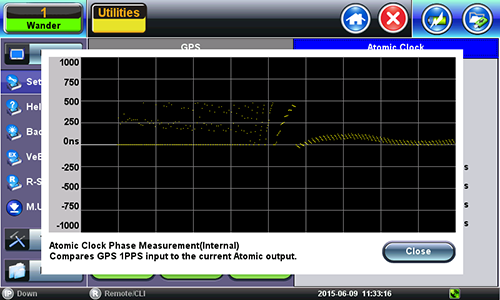
Example of GPS-disciplined Atomic relative phase convergence graph
-
Yellow dots indicate valid relative phase measurements (output - input).
-
Scattered yellow dots could indicate bad GPS/GNSS signal, which in turn provides bad timing accuracy, or that the oscillator trying to compensate for large phase differences.
-
White dots (line) at zero indicates loss of GPS 1PPS. It basically indicates holdover periods.
What you want to see in this graph is a tight bundle of differential phase measurements forming a line converging to zero and staying at zero. Since the Atomic Clock output is very stable, it will slowly try to infer the true (accurate) time alignment out of the GPS 1PPS output and maintain it. The less disperse the individual measurements (dots) are, the better the GPS timing signal is. So, you want to see a straight line formed by not-so dispersed group of dots.
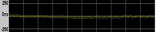
Example of proper (converged and stable) phase alignment
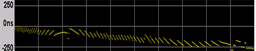
Not so good phase alignment
The chip scale atomic clock oscillator uses its 10 MHz frequency source for the disciplining process. Its 1PPS phase is initially aligned to the 10 MHz phase, so it should be within ±100 ns (one 10 MHz cycle). Then the CSAC would start steering its frequency to finely align its 1PPS output within a few nanoseconds to the “average” 1PPS input coming from the GPS receiver.
![]() In the context of this document the term “GPS Receiver” is not considered a synonym of “GPS Clock” or “GPS-disciplined Clock”. A GPS Clock is considered a combination of a GPS receiver and a highly stable precision oscillator.
In the context of this document the term “GPS Receiver” is not considered a synonym of “GPS Clock” or “GPS-disciplined Clock”. A GPS Clock is considered a combination of a GPS receiver and a highly stable precision oscillator.
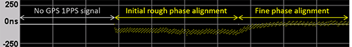
Example of initial phase alignment
Although the relative phase alignment may converge rather fast in many occasions, users must still observe the minimum recommended disciplining time.
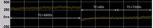
![]() If the disciplining time constant (TC) is changed in the middle of the process, from one long value to another, the phase may take long time to converge to zero or could display a somewhat erratic behavior for a while. In this scenario, if users need to change the TC, it may be worth temporarily changing it to a short TC (e.g. 60s) for faster steering and then change it to the desired value. (Note that although the Sync 1PPS button could also be used to force alignment of the Atomic 1PPS output, it does not adjust the required disciplining or steering parameters.)
If the disciplining time constant (TC) is changed in the middle of the process, from one long value to another, the phase may take long time to converge to zero or could display a somewhat erratic behavior for a while. In this scenario, if users need to change the TC, it may be worth temporarily changing it to a short TC (e.g. 60s) for faster steering and then change it to the desired value. (Note that although the Sync 1PPS button could also be used to force alignment of the Atomic 1PPS output, it does not adjust the required disciplining or steering parameters.)
 .
.
Using short TC to force quicker phase convergence to zero
Phase Alignment and Holdover
Knowing whether the oscillator is still steering (changing) its frequency to correct the 1PPS output’s phase has a big impact in deciding when to force the test set into holdover for indoors testing. The Phase Graph can help in identifying when the disciplining process has stabilized.
A disciplined oscillator will continuously adjust its frequency to keep the 1PPS aligned to the standard second, but those offset adjustments are usually small fractions of ppb when proper disciplining has been achieved.
Upon the loss of the GPS 1PPS reference, the oscillator enters holdover mode. This means that the precision oscillator will hold its last frequency and the phase error will continue its trend. That means, you want the instantaneous frequency to be as accurate as possible at the moment when the GPS receiver is turned off. Keep in mind that any ±X.XXX ppb frequency offset would result in a cumulative time error of ±X.XXX ns per second and that would impact the resulting usable holdover time, by reaching the defined error tolerance faster or slower.
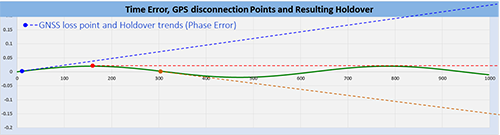
Illustrative examples of what would happen if GPS 1PPS is lost during different steering stages
Limitations: This method of determining proper 1PPS phase disciplining convergence would only work at the beginning of the disciplining process, which is what would be needed in the field.
Long-term, especially when long time constants are used, the oscillator will become hard to steer as it would be trying to hold what it “believes” is true time alignment, based on a long learning process. In this case, if the GPS receiver starts to wander and becomes somewhat inaccurate, the graph would show such discrepancy, but the oscillator’s 1PPS output would still be stable and accurate.
GPS instant accuracy could change within ±150ns during the course of a day depending on atmospheric conditions and satellites visibility. The job of the atomic clock is to filter those slow variations, so in the long term it is normal to see the GPS and CSAC phases temporarily disagree (relative phase ≠ zero).
Warm Up Times
All precision reference sources require a “warm up” time to achieve high accuracy and stability. The warm up term is being used loosely because it is not just about attaining the right temperature. It also includes disciplining of a local oscillator, negotiating and stabilizing a clock through protocol messages, etc. Each of the tasks involved takes time to stabilize before it can be used for testing.
Operational Temperature
It is still a major player in the warm-up waiting time and it all depends on the ambient temperature and the initial temperature of the test set. For example, a test set left in the trunk of a car in a winter night will take longer to reach operational temperature.
Atomic Clock Warm Up
If fitted with a chip-scale atomic clock, they are housed in a miniature oven to maintain its internal temperature constant in spite variations in ambient temperatures and it can take up to five minutes to warm up and should not be used until its status shows “Locked”. The atomic clock temperature and status can be monitored at \Utilities \Settings \More \High Precision Clock Source \Atomic Clock. The chip-scale atomic clock is oven-controlled and temperature-compensated to minimize the effects of ambient temperature variations.
Beside temperature, users must be aware of other factors that require time to settle, before accurate measurements can be made.
GPS Lock
The time to get an stable clock output varies depending on the conditions, antenna type and installation, sky visibility and whether or not the test set has changed position. Using the test set for the first time on a new site (different geographical position) would increment the time to its first satellite lock. Users can follow the different stages (Searching, Sync 1PPS, and Lock) by checking the GPS status GUI at >Utilities >Settings >More >High Precision Clock Source >GPS.
Disciplining Time
Disciplining the atomic clock means using the accurate GPS timing signal to correct or align the atomic clock output signals. GPS are known for their high accuracy as they are traceable to the universal time standard (UTC). Atomic Clocks are known for their great stability. So, the combination of GPS + Atomic Clock = Highly Accurate and Stable clock source. Achieving such levels of precision takes time. The total time to stable output depends on the precision required. The disciplining time can be programmed in the Atomic Clock settings and users must add it to the total “warm-up” time, before starting measurements.
Precision Timing Protocol
PTP, like IEEE 1588v2, require some time for the two ends (master and slave) to agree on the current time. This protocol “warm-up” time is dependent on the link conditions (traffic, latency, delay variations, PTP settings, etc.). Tests shall not be started until the protocol has stabilized and the recovered clock has achieved its maximum accuracy and stability. This is sometimes referred as “Convergence” or “Sync PDV” convergence. Users can use the long tail of the 1588v2 Sync PDV graph as an indication the PTP has reached synchronous state.