ViPAG/VRoute Test
ViPAG/V-Route can be accessed from the Test Mode menu. Refer to Test Port Selection for instructions on selecting Ethernet test modes.
The following selections are available on the unit:
-
SILO/Router Wrap Test: "On local unit" testing on a single unit.
-
End-to-End Test (VeEX to VeEX): "With remote test unit" testing.
-
Controller: Carries out the peer-to-peer/asymmetric handshaking, loads the remote profile to the remote unit, and initiates the test.
-
Responder: Establishes IP connectivity and waits for the controller to connect/initiate the test.
-
-
End to Loopback Test: One unit generates test traffic, while the other unit is set to loopback mode.
ViPAG/V-Route Setup
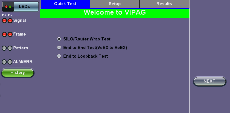
Quick Test Setup Welcome Page
![]() Quick Test menu options may vary depending on the unit you are using.
Quick Test menu options may vary depending on the unit you are using.
Quick Test Setup
Fill out each screen and press NEXT to proceed to the next page or Previous to go back to the previous screen.
-
Select the test type: SILO/Router Wrap Test, End-to-End Test (VeEX to VeEX), End to Loopback Test.
-
Step 1: Select the router test interface. "Local unit" denotes a router wrap test while "end-to-end" conducts an end-to-end test. For End-to-End testing, select whether this unit will be a Controller or Responder. For End to Loopback testing, select whether this unit will be Generating Traffic or in Loopback Mode. The frame size for each option listed below is 256 bytes. The following options are available:
-
1G to 1G: 1G interface is always set to 100% of the line rate.
-
1G to 10G: 10G interface is always set to 100% of the line rate.
-
1G-10G with remote test unit: For Copper or Fiber, Controller is set to 100% of the line rate; remote is 100% of the line rate.
-
10G to 10G: 10G interface is always set to 100% of the line rate.
-
10G to 1G: 1G interface is always set to 10% of the line rate.
-
-
Step 2 (SILO/Router Wrap only): Select the Layer.
-
Step 3: Configure port settings for port 1. Refer to Port Setup for detailed instructions.
-
Step 4: Configure port settings for port 2.
-
Step 5: The wavelength for the test ports are displayed. The Change button turns off the laser on the optical ports and pauses setup.
-
Step 6: Enter the local IP address for port 1. Press Apply and configure the subnet mask address. Press Apply and enter the gateway address. At the end of Step 4, the screen will display a summary of the IP address, Subnet, and Gateway. Tap on any of the corresponding fields to make any changes, if necessary.
-
Step 7: Enable up to 3 VLAN tags. Configure ID, Priority, Type, and Drop Eligible.
-
Step 8: Enter the IP address, Subnet, and Gateway for port 2, following the same procedure detailed in Step 4.
-
Step 9: Enter the frame size. The default frame size for each option is 256 bytes.
-
Step 10: Review the settings for both ports. Press Start to begin testing. Pressing Reconfigure will restart the Quick Test Setup and return the screen to Step 1.
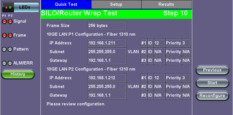
Step 10: Review Configuration
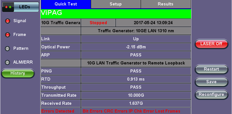
Quick Test View
After starting the test, the Error Injection button for each port becomes available and the screen displays Quick Test view and the following results for both ports:
-
Link Up/Down status.
-
Optical Power in dBm.
-
ARP - Pass/Fail status.
-
PING - Pass/Fail status.
-
Round Trip Delay (To Ping Round Trip Test Time) measurement in ms.
-
Throughput - Pass/Fail status.
-
Transmitted Rate.
-
Received Rate.
Quick Test View
In case of link or IP related test failure, ViPAG will indicate the possible failure in red text and give instructions on what to check for.
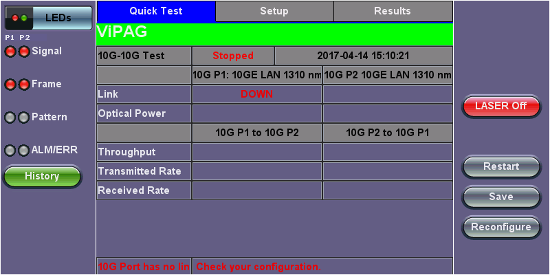
Test Failure
Setup
Test sets come preconfigured. To customize settings for both ports, go to the Setup tab. For configuration instructions, please refer to BERT.
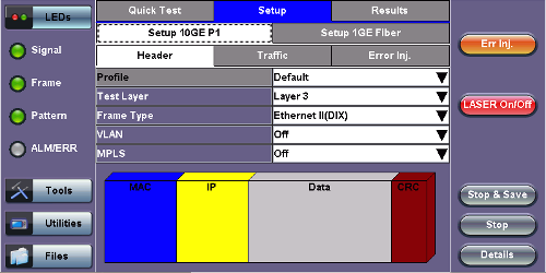
Setup
Results
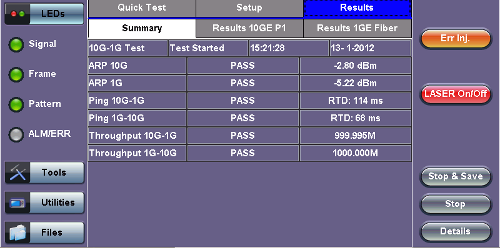
Summary Results
The Summary tab lists the Pass/Fail status of each ARP, Ping, and Throughput test along with test measurements.
The Results tabs for each port lists statistical results similar to those featured in the BERT Results section. Please see BERT Results for more information.
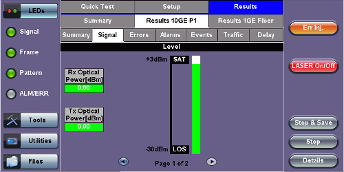
Port Results