Peer-to-Peer and Asymmetric Testing
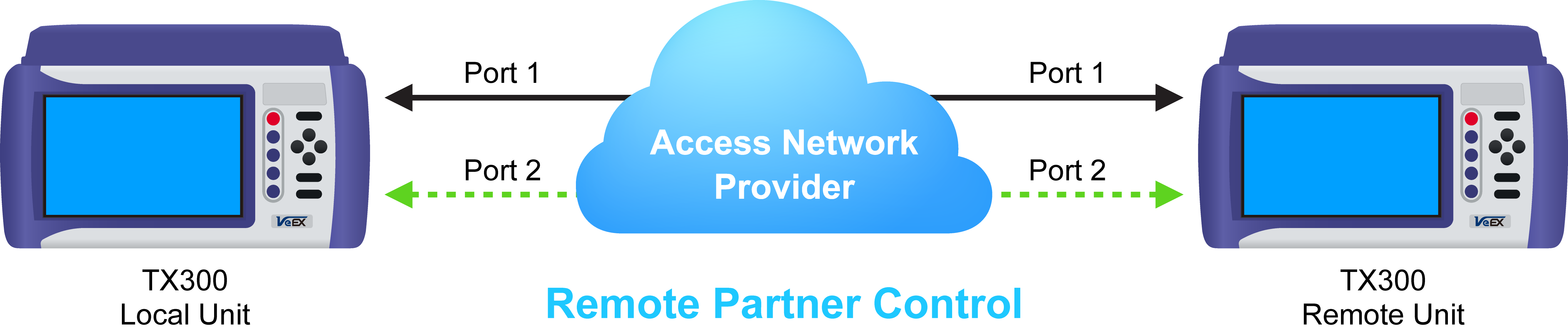
Remote Partner Control
When the local unit connects to the remote (peer) partner, it loads the same configuration profile (header, traffic, and frame size) to the remote partner, with the MAC and IP addresses inverted. From the peer-to-peer menu, asymmetric testing becomes available.
Asymmetrical links provide different line rates in the two directions. To verify the information for both the low and the high rates of the link, the user needs to send a test signal from one instrument located at one end of the link to an instrument at the other end of the link and vice versa to test traffic capacity. The two test instruments have to be synchronized because the tests defined in RFC 2544 require the receiver to know the contents of the test signal to be transmitted in detail.
The test set offers an automated RFC 2544 test application to perform throughput, frame loss, and burstability tests in a local-remote unit setup. The user first configures the test setup in the local unit. Once initiated, the local unit transfers the setup information to the remote unit via the line under test. Upon completion, the remote unit transfers the test results back to the local unit, enabling the user to read the results for both directions of the link on the local unit.
Asymmetric Testing Setup
- Tap the P2P Setup button on the right side of the screen to start the step-by-step setup process.
- Set the Local unit as a Controller or Responder.
At any time during the process, tap on the right side navigation buttons to move to the NEXT screen, return to the Previous screen, or Exit the setup guide.
Set the Local unit as Controller or Responder
Unit as Controller Setup Process
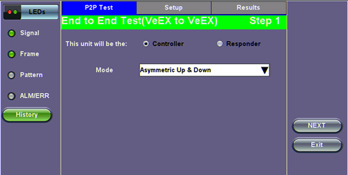
- Step 1: Select Controller.
- Mode: Select an asymmetric test configuration.
- Asymmetric Up: Tests traffic in the upstream direction (local to remote direction).
- Asymmetric Down: Tests traffic the downstream direction (remote to local direction).
- Asymmetric Up & Down: Test traffic in both upstream and downstream direction.
- Mode: Select an asymmetric test configuration.
- Step 2-7: Make the following selections for the Controller and Remote units: Layer, IP Address, Subnet, Gateway, and VLAN tags. Tap on the white fields to edit options. Use the alphanumeric keyboard to input parameters and press Apply to save edits.
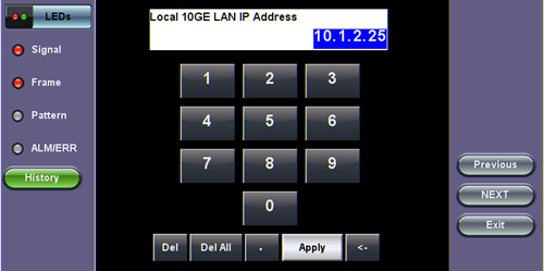
Input screen
- Step 8: Tap on the check boxes to add local frames. Tap on the Add Frame button to add a customized frame size.
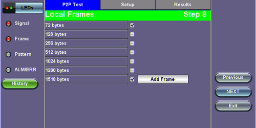
Controller - Step 8
- Steps 9-12: Set up and enable/disable tests for the Local unit.
- Step 9: Local Throughput testing setup. See the Throughput section for a description of menu options.
- Step 10: Local Frame Loss testing setup. See the Frame Loss section for a description of menu options.
- Step 11: Local Burst testing setup. See the Burst (Back-to-Back) section for a description of menu options.
- Step 12: Local RX Thresholds setup. See the Thresholds section for a description of menu options.
- Steps 13-16: Set up and enable/disable tests for the Remote unit. See Steps 8-11 for information on setting up individual tests.
- Step 17: Review configuration selections on the summary screen. The option to Start testing or Reconfigure test settings becomes available.
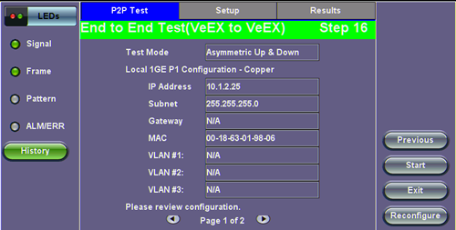
Controller Summary Screen
Unit as Responder Setup Process
- Step 0-2: Tap on the white fields to setup the Local unit's IP Address, Subnet, and Gateway. Tap on Next to setup VLAN tags using the drop-down menu.
- Step 3: Review configuration selections. The option to Start testing or Reconfigure test settings becomes available.
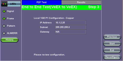
Responder Summary Screen
RFC 2544 Local and Remote Test Setup
RFC 2544 Test setup for the local and remote unit is available in the Setup tab. Refer to Setup - Standard Mode for more information.
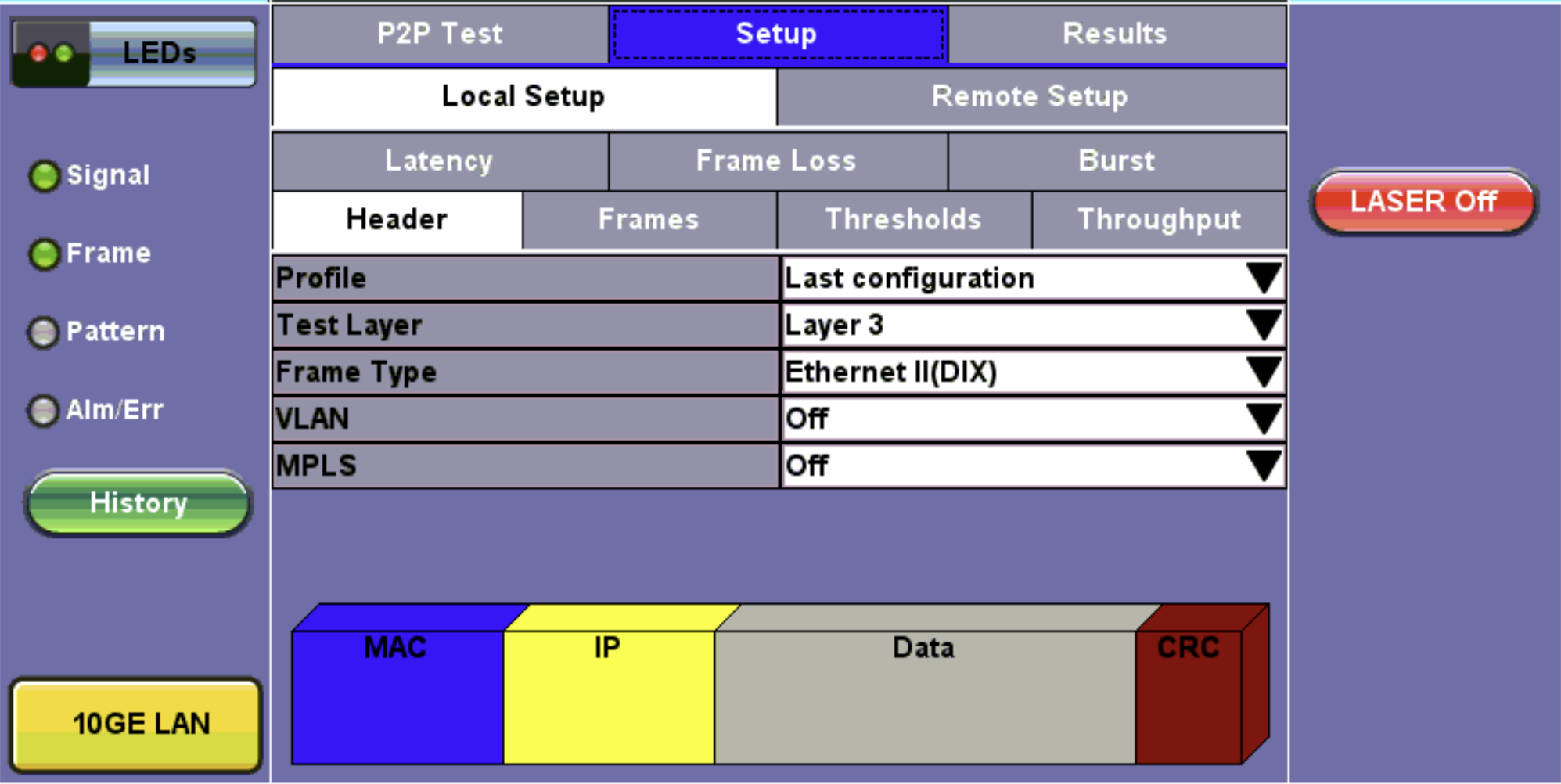
Local Setup
Test Results
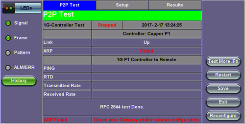
P2P Test Results
While the test is running the options to Stop the test, Stop and Save results, and view result Details appear. After testing finishes, the option to test More IPs, Restart, or Save test results become available as right side buttons.