Test Results
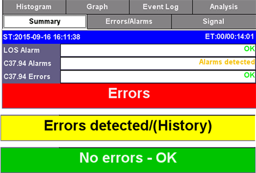
In general, the following color coding is used to identify the status.
-
Red: Errors or alarms are present.
-
Yellow: Errors or alarms have been detected but no longer present.
-
Green: Good! No errors or alarms have been detected.
Summary
Shows the overall status of the current test.
-
ST: Start Time. Date and time when the test started.
-
ET: Elapsed Time. Total time that the current test has been running.
-
RT: Remaining Time. During timed tests it indicates how much time is still left before the test stops.
The bottom banner shows the overall status, while the individual fields at the top provide more information about which layers may have been affected.
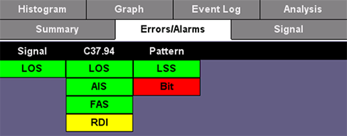
Errors/Alarms
The first page of this detailed test results report shows a layer-by-layer summary of all Alarms and Errors being monitored. Tap on the individual indicators to quickly access detailed count and rate measurements. The arrow buttons at the bottom can also be used to navigate the results page by page.
Signal
All physical layer information can be found in this tab.
-
Level: Received optical power readings as reported by the transceiver. Presented in numerical and graphical format.
-
Frequency: Received clock measurement and clock offset calculation in parts per million (ppm).
-
Optical: Displays transceiver related information.
-
SFP: Graphical display of received power level fluctuations over time.
Histogram
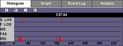
Shows the sequence of errors and alarms over time. It can be used to correlate intermittent problems to other events (e.g. power loss, storms, vibration, etc.) or identify if the problem is cyclic or random in nature. User can zoom in and zoom out using the [+] and [-] buttons to view the results in hours, minutes or seconds. In zoom mode, use the [<] and [>] buttons to navigate the different time windows.
Event Log
Shows a time-stamped sequence of all events detected during the test, including the length or error count for each of the events.
Analysis
Shows G.821 out-of-service (OOS) BER performance analysis with Pass/Fail evaluation. Errored Second (ES), Severely Errored Seconds (SES), Available Seconds (AS), Unavailable Seconds (UAS), Error Free Seconds (EFS).
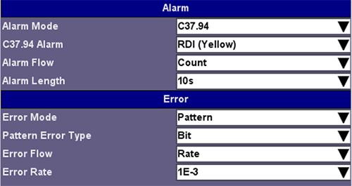
Alarm / Error
Configures the behavior of the Alarm Generation and Error injection soft buttons.
-
Alarms: The test set can generate Signal-based LOS, Frame-based LOS, AIS and RDI (Yellow), in Continuous or Count (timed) modes. In timed mode the alarms can be set to last 0.1, 1, 10 or 100 seconds.
-
Errors:
-
Error Mode: The test set can inject errors to the C37.94 structure or to the test Pattern.
-
Error Type: FAS, Bit
-
Error Flow: Determines the behavior of the error injection. It can be set to inject a Single error, a Count or specific number of errors from 1 to 1000, or a continuous error Rate from as low as 1E-9 (1x10⁻⁹) to as high as 1E-3 (1x10⁻³).
-