One Way Delay Measurements (Latency and Asymmetry)
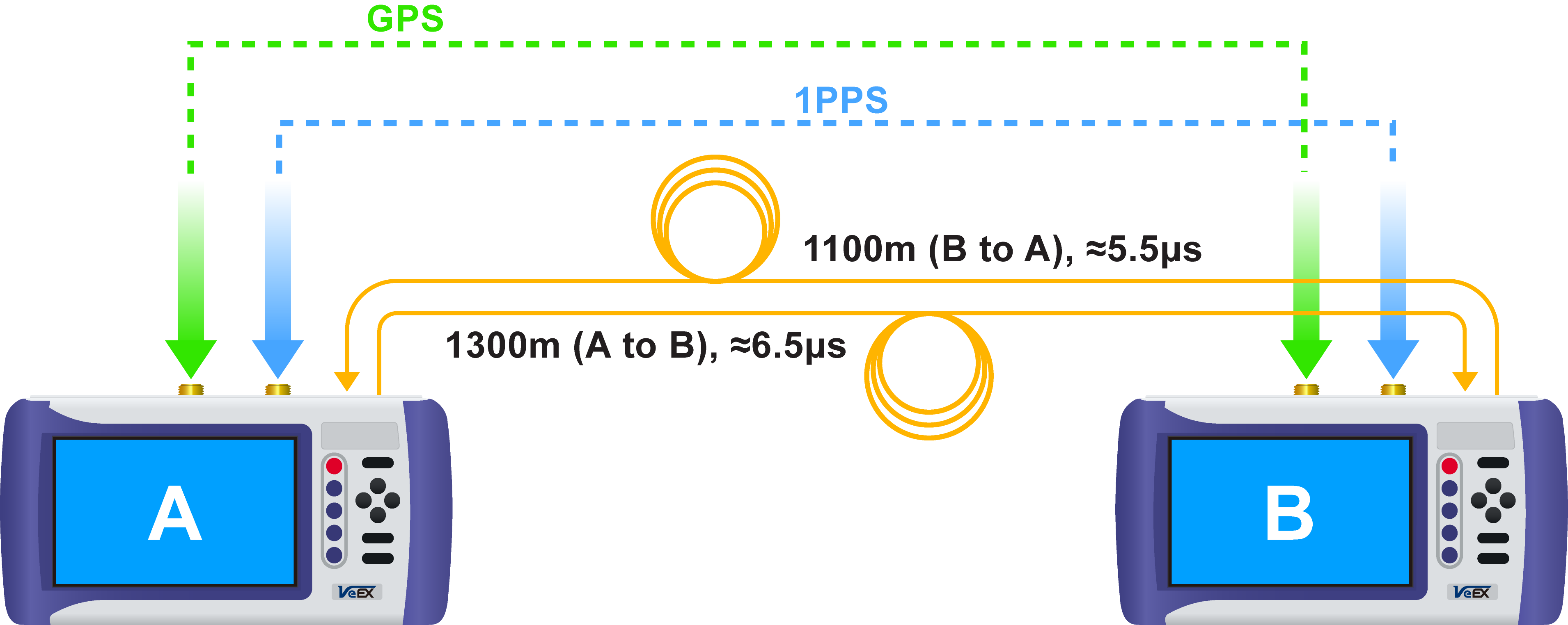
Certain timing-sensitive applications require symmetric data links so a dual-ended One-Way Delay (OWD) test is required to verify the data latency in each direction of the link. The two test sets used, one at each end, require access to accurate time. This timing source is provided by a 1PPS signal from GPS Clock (built-in or external). The rising edge of the one-pulse-per-second signal indicates the beginning of a second everywhere in the world. The 1PPS is used to synchronize the clocks in both test sets.
The OWD test must work with C37.94 bursty behavior (data transmitted every 125μs) and be compatible with any Nx64k data rate, network element, multiplexer, DSn, PDH, SDH or SONET equipment in the path, to achieve meaningful resolution and accuracy.
OWD is a coordinated test that requires both test sets (and users) to be ready and following each other’s status over the phone or any other communication mean. Users in sites A and B must have access to:
-
A traceable External 1PPS signal (from a GPS clock) connected to the test set’s CLK (SMA) input port, or
-
The built-in GPS option in the test set and have its antenna installed with unobstructed wide view to the sky.
For the built-in GPS receiver:
-
Connect the antenna to the SMA connector.
-
Go to Utilities >Settings >More >High Precision Clock Source >GPS and turn GPS ON. Wait until satellites are detected (at least four with >36 dBHz) and the GPS Status = Lock (the GPS button
 on the bottom-right of the screen turns green).
 -
Notify your partner at the far end and go back to the C37.94 app to begin testing. This is not required if an External 1PPS is used as reference.
-
Once both test sets are synchronized to the standard second (1PPS), connect them to their respective local C37.94 ports, turn the laser ON and verify proper end-to-end connectivity (Signal, Frame, Pattern and no errors or alarms).
-
Enter the One Way Delay function and confirm with the far-end that they are also in the OWD measurement screen. Press the Start button to start measuring the incoming delay (Return Path) and receiving the outgoing delay from the far end (forward path).
Network elements and multiplexers are usually responsible for most of the latency added to the path (link), with fiber being responsible for adding around 0.5μs for every 100m of cable. The example diagram only includes the fiber part of the link, as it is considered the worst case scenario (shortest delays) and highlights the importance of having enough accuracy and resolution (1μs or better) in order to measure cables’ contribution.

One-Way Delay: Site A to B
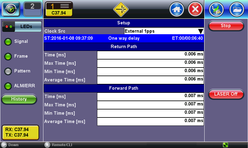
One-Way Delay: Site B to A
Keep both test sets in the One Way Delay screen. If one of the test sets leaves the OWD test feature, the other test set may start reporting invalid results. Stop the test and save the results before quitting the OWD application.
In Dual Port mode, the test set allows running a bi-directional OWD test with only one meter. This is useful for troubleshooting problems in a lab or repair center or fine-tuning network settings when access to both ends of the links are available in one site.
![]()