Jitter Transfer Function (JTF)
Jitter Transfer defines the ratio of output jitter to input jitter amplitude versus jitter frequency for a given bit rate.
Often, a portion of received jitter is transmitted at a piece of the equipment's output. If LOS is detected during the JTF test, the test will be stopped.
-
Calibration
Using a short and clean patch cord, connect the test set's TX back to the RX to form a local reference loop.
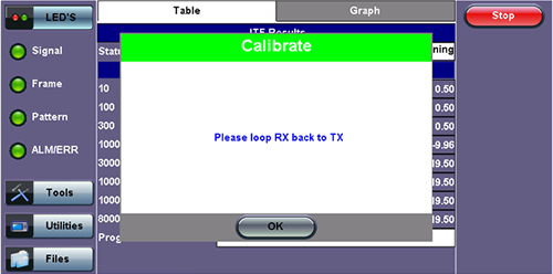
Loop Message
-
Device Under Test (DUT)
Before starting the test, "Connect Device Under Test" will appear. Connect the test set to the DUT then press Start to begin testing.
-
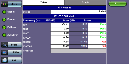
Frequency (Hz): Frequency measured
-
JTF (Jitter Transfer Function) (dB): Jitter in divided by jitter out value (in dB)
-
Mask (dB): Jitter output in relationship to the input
-
Progress: The bar at the bottom of the graph shows the test progress
-
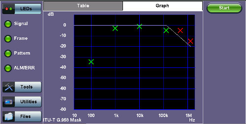
A green cross (x) indicates the the jitter transfer value has passed.
A red cross (x) indicates that the jitter transfer value has failed.
Yellow triangles (▲) indicate that the jitter transfer value is greater than the value measured by the test set.