Fiberscope Setup
Captured patch cord image files are saved within a folder directory. In the Setup tab, name each folder and file in the directory and select a save increment.
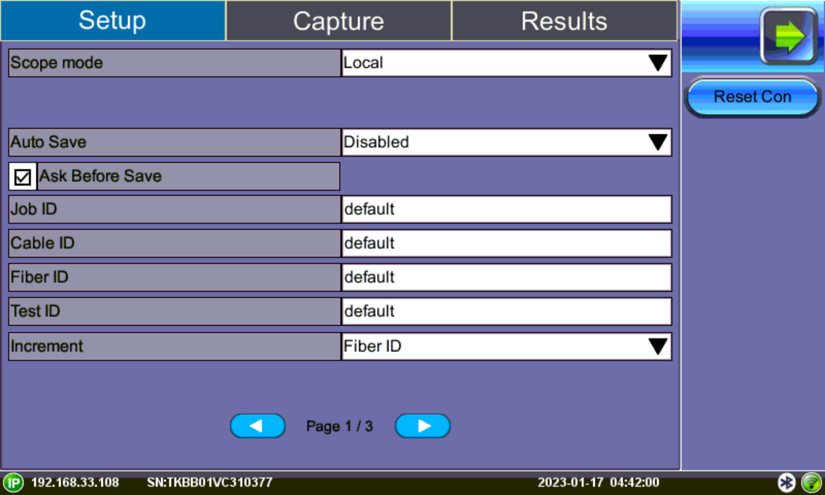
Fiber Scope Setup - Page 1
-
Scope mode: Sets Fiber Scope connection method.
-
Local: Direct USB (wired) connection.
-
Remote DI-3000: Wifi connection to DI-3000.
-
-
Reset Con: Resets connection method currently used (Remote or Local) with fiberscope, so another can be selected.
-
Auto Save: Disable, Autosave on Tap, or Autosave after freeze. If Autosave on Tap or Autosave after freeze is enabled, the unit automatically saves and creates the filename using the Trace ID after the test. The file location and name will display. Auto Save is available for single fiber analysis only.
Disabled: Turns off Autosave function. When Autosave is disabled, results can be manually saved on the Results tab after finishing the fiber endface inspection.
Autosave on Tap: On the Capture tab, tap the screen to automatically save the captured image. “Tap screen to save” will appear to indicate that the feature is enabled.
Autosave after freeze: Automatically saves the captured image upon freezing the image. (Auto-freeze enabled or normal Freeze.)
When Ask Before Save is selected, the Save menu will display with naming and comment options.
The details entered in the following fields can be used to pre-set the filename automatically and increment the fiber or test number automatically.
-
Job ID, Cable ID, Fiber ID, and Trace ID are nested folders that store saved results. Folders are nested in the following order: Job > Cable > Fiber > Trace.
Tap the blank fields to edit the names.
-
Increment: Increments the selected ID name if an Auto Save option is selected.
Saved image files can be retrieved from File Manager or managed from the Results tab. Refer to Working with Saved Results, Profiles, Images for more details.
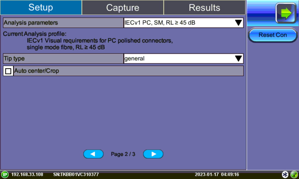
Fiber Scope Setup - Page 2
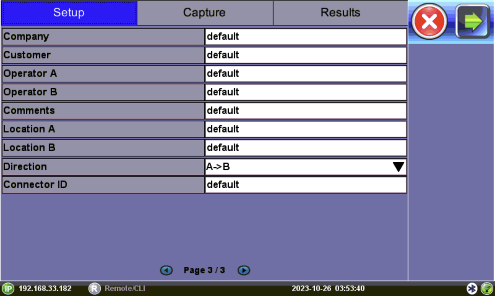
Fiber Scope Setup - Page 3
Analyze Fiber Connectors
-
After assigning the scope mode and save options on Page 1, select the analysis profile from the Analysis parameters drop-down box on Page 2/2 of the Setup tab.
The analysis profile is based on the fiber endface connector inspected, as well as applicable to MTP™/MPO (multi-fiber) connectors. .-
PC, SM RL ≥ 45 dB: SPC or UPC polished connector
-
PC, SM RL ≥ 26 dB: Older connectors with flat or PC polish (used with LC/MU)
-
APC, SM: Angled polished connector
-
-
Select the Tip Type from the drop-down box. Tip Type is used to optimize Pass/Fail analysis for certain types of connector tips.
-
General: Encompasses standard SC, FC, ST, and other 2.5 mm ferrules. LC/APC and E2000/APC should not use general tip type.
-
LC: Lucent connector (male). Use on all 1.25 mm connectors with ceramic (LC/MU connectors).
-
LC female: Lucent connector (coupler/bulkhead). Use when inspecting 1.25 mm type patch panels, MUX and test ports.
-
E2000™: Proprietary family of connectors invented by Diamond SA known for its low insertion loss characteristics and built-in (latched) shutter. Use when inspecting Diamond E2000 connector with ceramic ferrule.
-
E2000/APC Metal: Use when inspecting Diamond E2000 APC connector with metal ferrule.
-
Evolv™: Use when inspecting Corning Evolv terminal connector ports.
-
LC APC short extended A6 female: Use when inspecting hard to reach LC/APC connector coupler/bulkhead.
-
MPO PC female: Use when inspecting SM ribbon cables with MPO/MTP via coupler.
-
MPO APC female: Use when inspecting SM ribbon cables with MPO/MTP angle polished connector via coupler.
-
MPO MM female: User when inspecting MM ribbon cables with MPO/MTP connector via coupler.
-
-
After the image is frozen, select the Auto center/Crop checkbox to take the current video frame and center it by the detected fiber image inside the program window, i.e. in case of long (extension) tips or handshaking. Initially, a blank screen will display. This is ideal for APC images. This is recommended when inspecting Angled bulkheads/couplers with Shake OFF.
-
Select the Capture tab.