Hardware Configuration
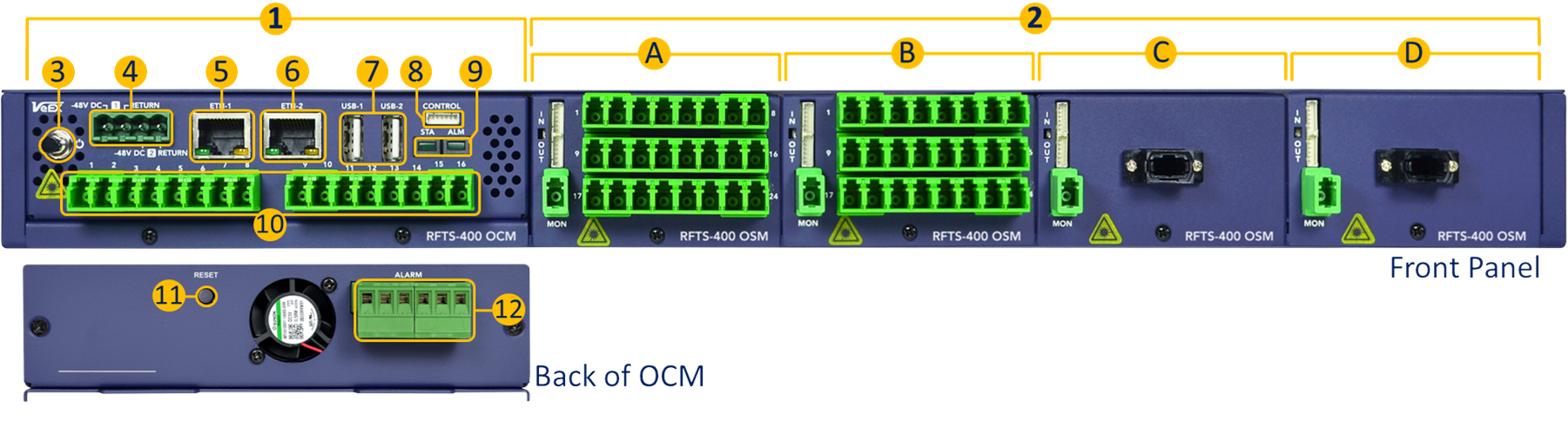
1. Optical Control Module (OCM) – This self-contained system provides local processing, analysis, data storage, control, scheduling, user interface, network access, a built-in OTDR engine and optional primary optical switch (up to 1x16 ports). A standalone OCM is considered a small RFTS system on its own.
2. Optical Switch Modules (OSM) – The main RFTS-400 chassis, with an OCM, can host up to four 1x24 optical switches or six on an empty 1RU shelf. OSMs are available with LC connectors.
3. Power Button.
4. Dual -48VDC Power Inputs.
5. Management Controller Unit (MCU) Ethernet port (system configuration)
6. OCM Ethernet Port.
7. USB-A Ports.
8. Control Interface (OUT) - This serial port controls daisy-chained OSMs. Connect to the first OSM module. It also provides power to the OSMs.
9. Status (STA) and Alarm (ALM) indicator LEDs.
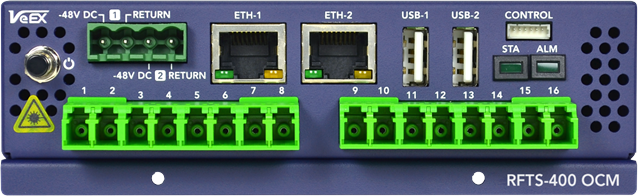
10. OCM Test Ports - Main built-in Optical Switch (up to 1x16) provides the test signals.
11. Reset Button - Brings the RFTS-400 MCU back to its factory default configuration.
12. Alarm Relays.
13. Ground Terminals - The grounding screws are located on both side walls of the rack tray, towards the back.
For ease of reconfiguration and maintenance, the modules are inserted from the front and secured with one screw, below the connector panel.
Optical Switch Modules and OXC Switches
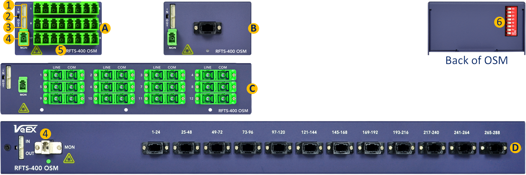
Different OSM can be selected depending on the application and desired monitoring port density:
A. 1x24 LC-APC Optical Switch Module (OSM), single slot.
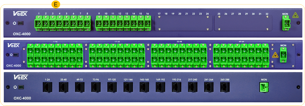
B. 1x8-288 OXC Ethernet controlled switches
![]() For custom configurations, contact your sales representative.
For custom configurations, contact your sales representative.
-
Control Input (IN) - Connects to the OCM's control (first module) or to the previous OSM OUT.
-
Module's power indicator (LED)
-
Control Output (OUT) - Connects to the next OCM IN.
-
Monitor Port - Connects to one of the OCM (OTDR) ports.
-
Test Ports - Connect to the different fiber links being monitored.
-
RFTS-400 module addressing DIP switch, located on the back of each OSM module.
Scalability
On the upper end, a single 16-port OCM can drive up to sixteen 288-port MPO OSM switches, for a total of 4608 test ports.
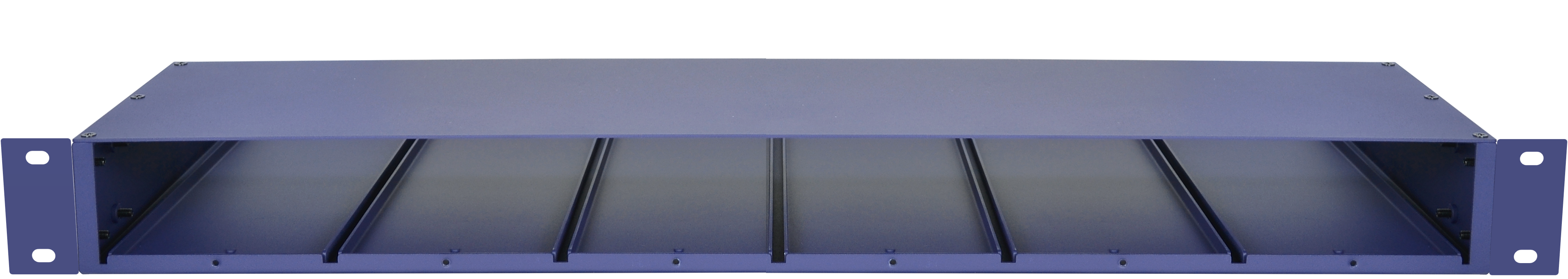
Empty 19" RFTS-400 1U rack tray, with six module slots
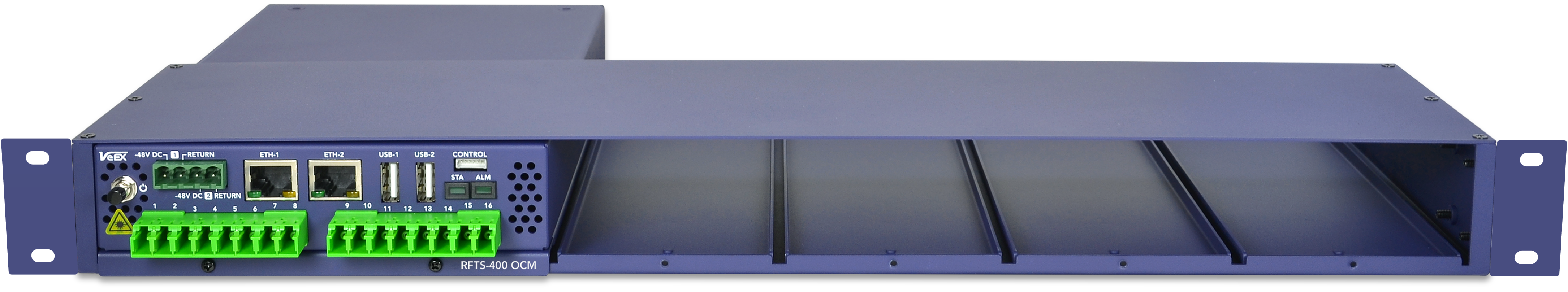
RFTS-400 chassis with one Optical Control Module (16 ports)
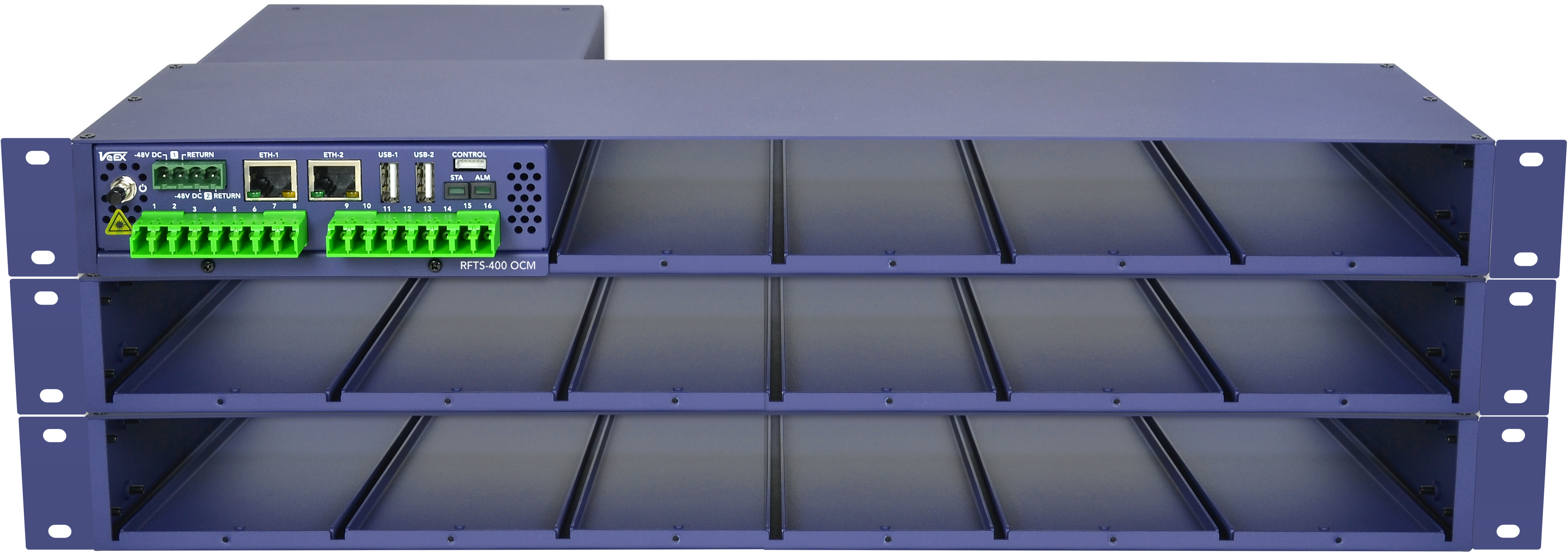
Three RFTS-400 trays with one OCM and capacity up to 16 switches (384 ports)
OCM Hardware Features
-
Integrated optical switch (up to 16 ports)
-
Up to 50 dB DR
-
500k datapoints
-
Supports both the Dark & In-Service monitoring
-
Non-intrusive Link Characterization features
-
Designed to monitor P2P & P2MP networks
-
OLS support including modulations for LFI
-
Works with any RFTS-400 OSM or OXC switch
-
Designed to run 24/7 in harsh environment
-
Redundant -48VDC supply
-
2 Ethernet ports
-
Main Ethernet interface
-
Dedicated Out-Of-Band management interface
-
-
Hardware design optimized to improve the OCM MTBF
-
Running on ruggedized Linux OS
Adding OSMs (Optical Switch Modules)
Connect Hardware
RFTS-400 OCM monitoring can be expanded with up to 16 RFTS-400 OSM modules (using three modular rack trays). The Control interface on the RFTS-400 OCM front panel is dedicated for communication with the optional RFTS-400 OSMs. Multiple RFTS-400 OSM modules can be connect to another RFTS-400 OSM, in a daisy-chain fashion, allowing a single RFTS-400 OCM to manage up to 16 RFTS-400 OSM switches.
|
|
RFTS-400 OSM modules cannot be connected or disconnected while the system is running. It is essential to power off the RFTS-400 OCM before adding a new RFTS-400 OSM module. |
|
|
Each RFTS-400 Optical Switch Module requires a unique switch ID, which can be configured using the DIP switches located on the back of the module. Please use the RFTS-400 Switch management software feature to help set the correct switch ID. |
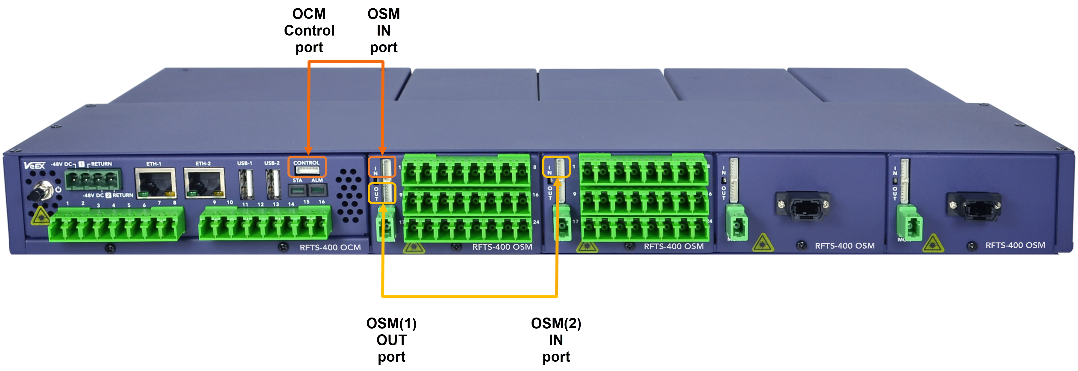
Use the control cable, included with each RFTS-400 switch, to connect multiple OSMs in series. When connecting the first switch module to the RFTS-400 OCM, use the control cable to make a connection between the OCM Control port on the and the IN port on the first OSM.
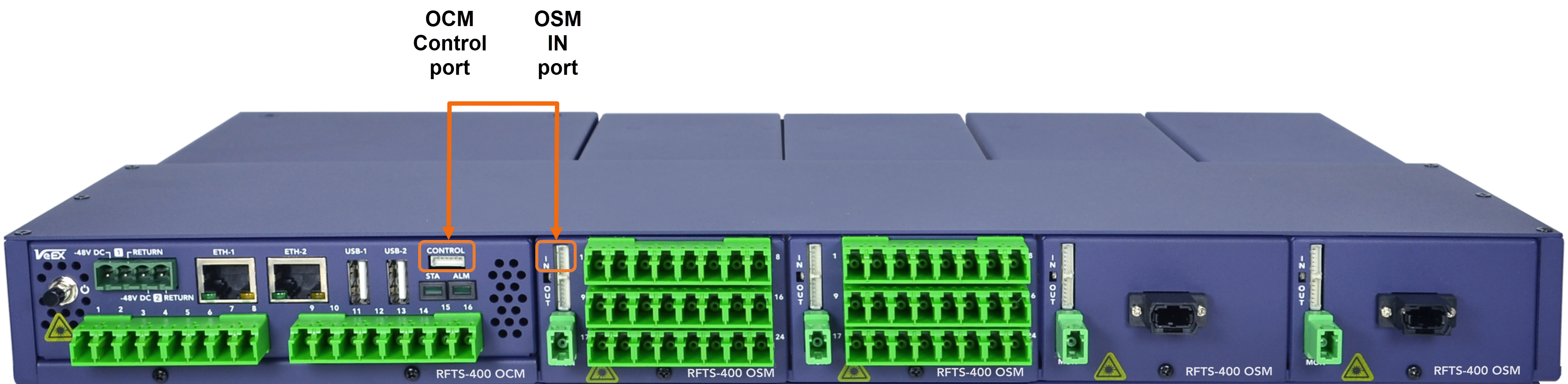
Every additional RFTS-400 OSM module is daisy-chained to the previous switch module, by connecting the OUT port to the IN of the next OSM.
Configure Ports using Management Software
Follow the DIP switch configuration for proper addressing of each of the optical test access units (OTAU) in the system, such as OSMs. Information about the individual DIP switch settings for each OSM can be found at RFTS Setup ![]() > RFTS Platform>OTAU Management.
> RFTS Platform>OTAU Management.
OSM Switch
-
Select the OCM port that will be connected to the MON port of the OSM and click Add OTAU. The identification number for the OSM is determined by the port number of the OCM.
-
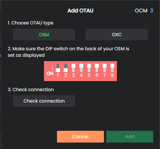
On the Add OTAU screen, choose the OSM switch type and click Add.
-
Ensure that the Optical Switch Module (OSM) has the matching switch ID as displayed in the User Interface (UI).
-
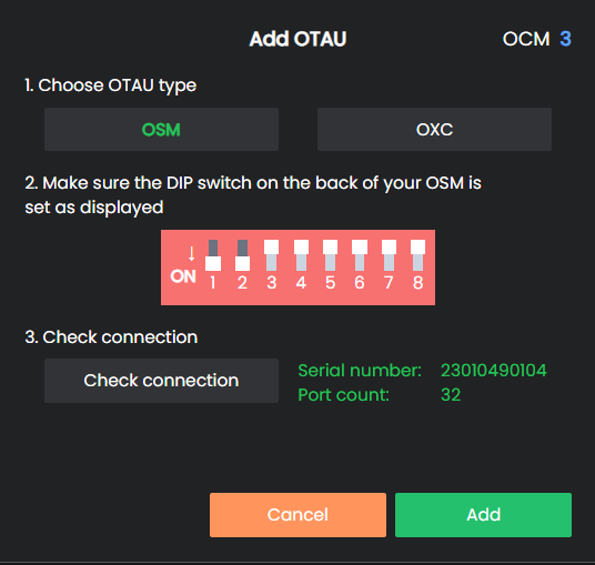
Click Check connection to confirm the communication status between the Optical Switch Module (OSM) and the Optical Control Module (OCM). Ensure that the system reads the OSM port count and the serial number by verifying that both values match the newly added OSM module.
-
Select the Add button to create and store the new optical switch cascade configuration.
![]() The OSM module ID is a logical address used by the OCM for signaling exchanges between the OCM and any particular OSM. This ID is independent of the physical OSM position or control wiring sequence (daisy-chain order).
The OSM module ID is a logical address used by the OCM for signaling exchanges between the OCM and any particular OSM. This ID is independent of the physical OSM position or control wiring sequence (daisy-chain order).
OXC-4000 Switch
-
On the Add OTAU screen, choose the OXC switch type.
-
Enter the IP address for the switch and select Check connection to confirm the communication status.
-
Once confirmed, select Add.