RFTS-400 Configuration Guide
VeEX's RFTS-400 modular platform is a self-contained Remote Fiber Test (monitoring) System capable of operating in serverless mode or as part of VeSion® centralized monitoring system.
Its design incorporates an Optical Control Module (OCM) and Optical Switching Modules (OSM) that support fiber monitoring expansion from 8 to 108 ports in a single 1RU rack enclosure, using four OSMs with the standard LC/APC connectors, or up to 108 ports using three 1RU trays. A fully expanded system can support up to 4608 monitoring ports.
Hardware Configuration
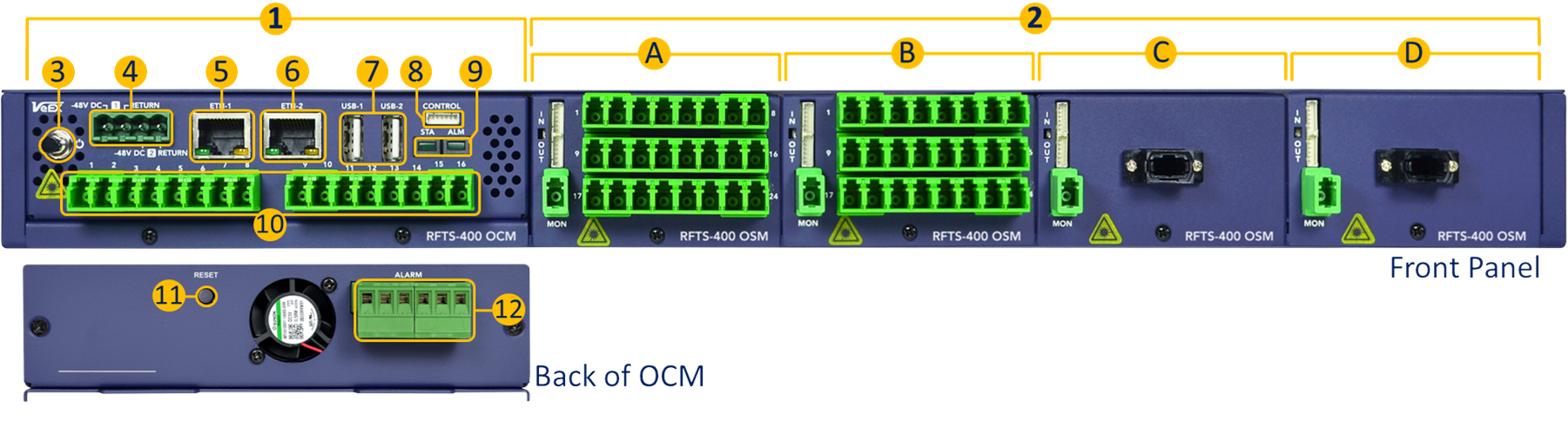
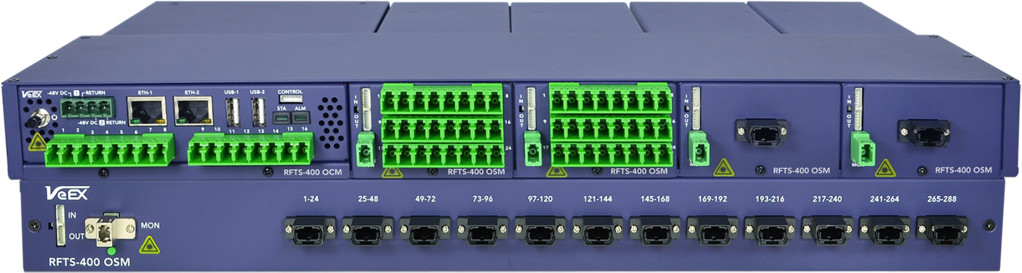
1. Optical Control Module (OCM) – This self-contained system provides local processing, analysis, data storage, control, scheduling, user interface, network access, a built-in OTDR engine and optional primary optical switch (up to 1x16 ports). A standalone OCM is considered a small RFTS system on its own.
2. Optical Switch Modules (OSM) – The main RFTS-400 chassis, with an OCM, can host up to four 1x24 optical switches or six on an empty 1RU shelf. OSMs are available with LC connectors.
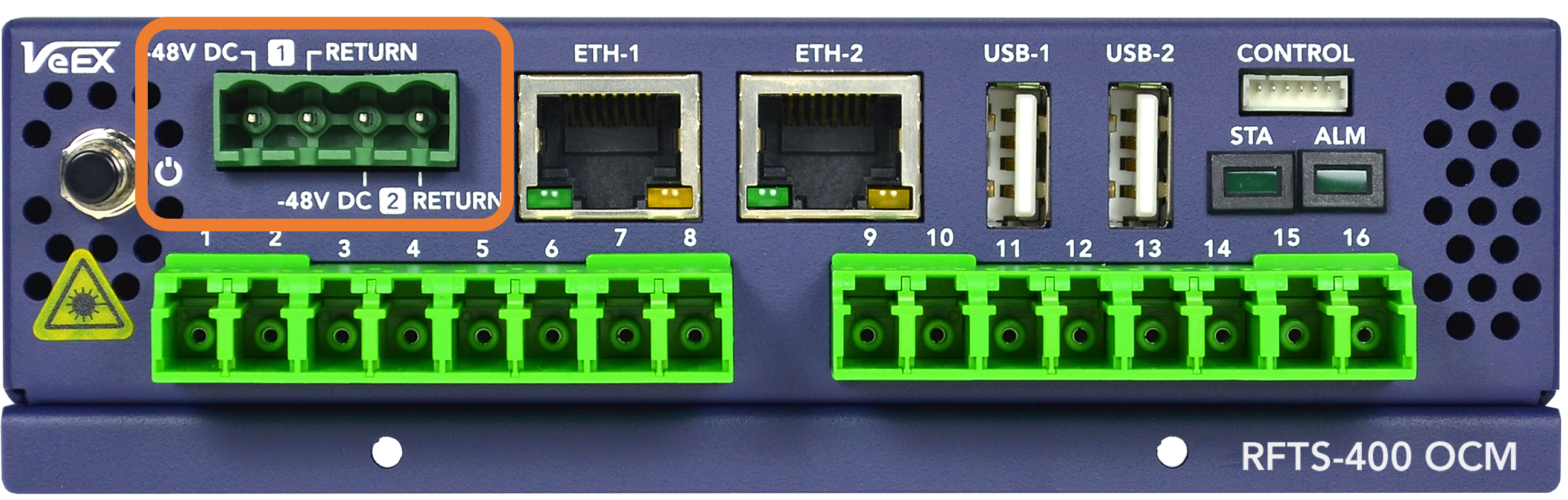
3. Power Button.
4. Dual -48VDC Power Inputs.
5. Management Controller Unit (MCU) Ethernet port (system configuration)
6. OCM Ethernet Port.
7. USB-A Ports.
8. Control Interface (OUT) - This serial port controls daisy-chained OSMs. Connect to the first OSM module. It also provides power to the OSMs.
9. Status (STA) and Alarm (ALM) indicator LEDs.
10. OCM Test Ports - Main built-in Optical Switch (up to 1x16) provides the test signals.
11. Reset Button - Brings the RFTS-400 MCU back to its factory default configuration.
12. Alarm Relays.
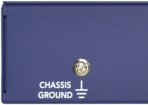
13. Ground Terminals - The grounding screws are located on both side walls of the rack tray, towards the back.
For ease of reconfiguration and maintenance, the modules are inserted from the front and secured with one screw, below the connector panel.
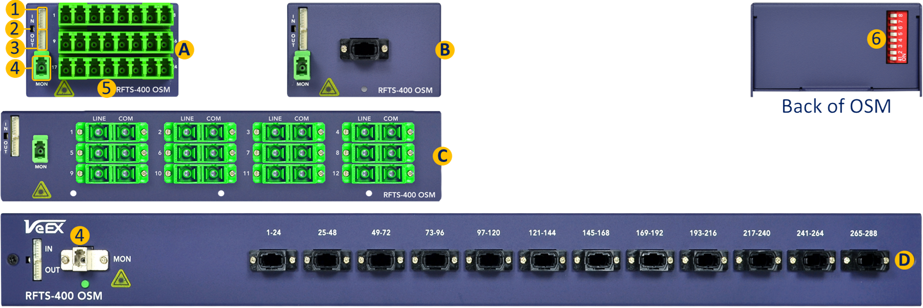
Different OSM can be selected depending on the application and desired monitoring port density:
A. 1x24 LC-APC Optical Switch Module (OSM), single slot.
B. 1x8-288 OXC Ethernet controlled switches
![]() For custom configurations, contact your sales representative.
For custom configurations, contact your sales representative.
-
Control Input (IN) - Connects to the OCM's control (first module) or to the previous OSM OUT.
-
Module's power indicator (LED)
-
Control Output (OUT) - Connects to the next OCM IN.
-
Monitor Port - Connects to one of the OCM (OTDR) ports.
-
Test Ports - Connect to the different fiber links being monitored.
-
RFTS-400 module addressing DIP switch, located on the back of each OSM module.
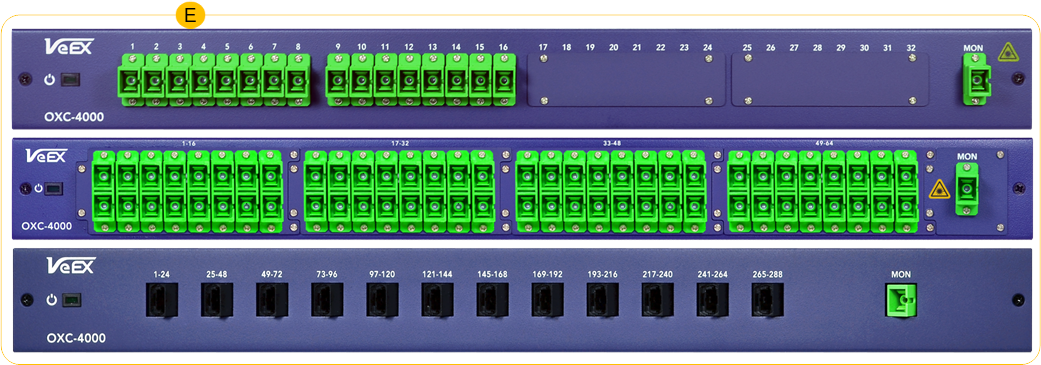
On the upper end, a single 16-port OCM can drive up to sixteen 288-port MPO OSM switches, for a total of 4608 test ports.
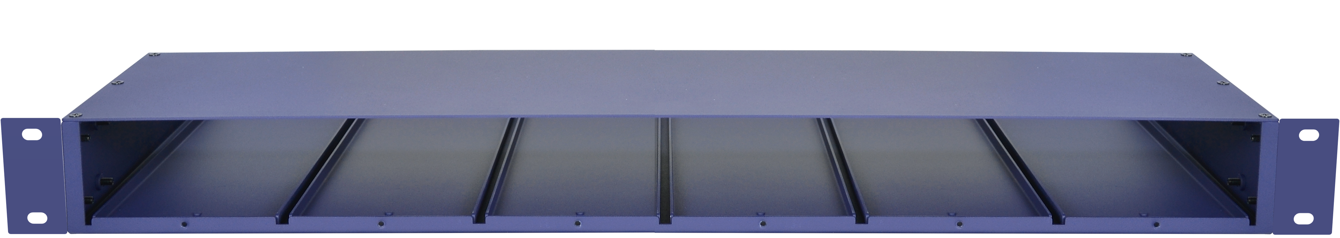
Empty 19" RFTS-400 1U rack tray, with six module slots
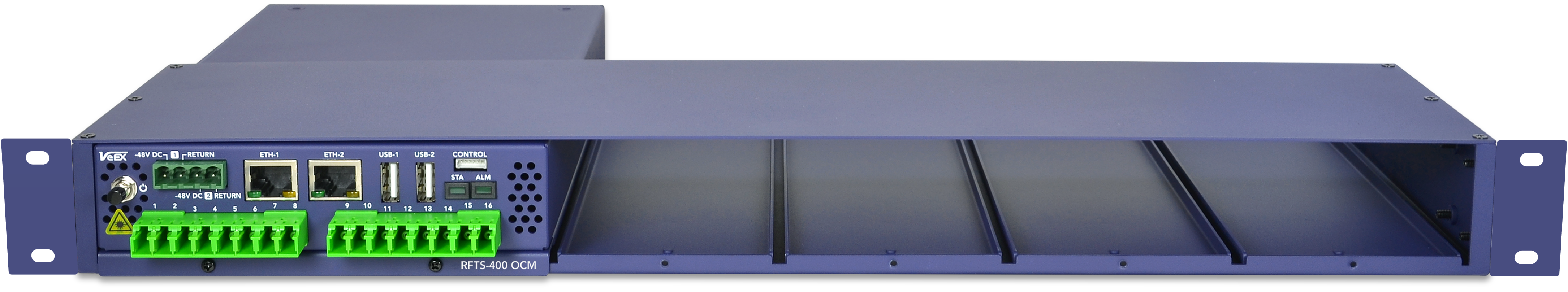
RFTS-400 chassis with one Optical Control Module (16 ports)
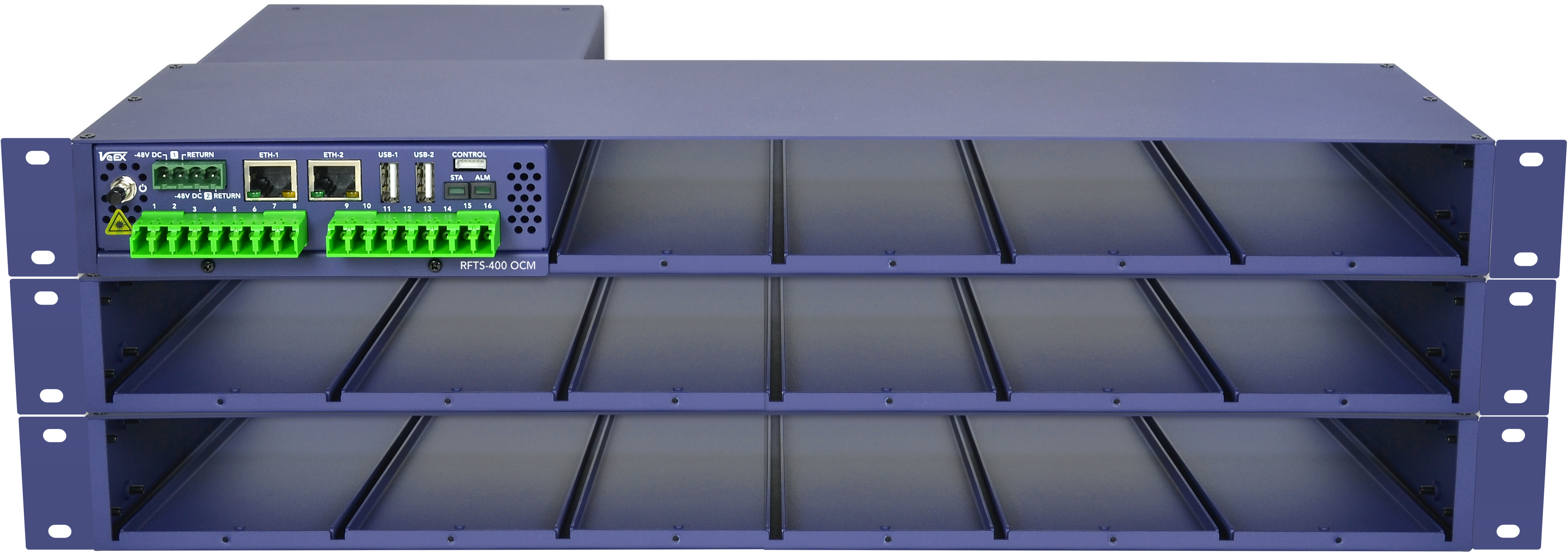
Three RFTS-400 trays with one OCM and capacity up to 16 switches (384 ports)
Install Hardware and Connect Power
![]() Users should be familiar not only with rack mounting and cabling, but also with electronic circuitry, wiring practices, and safety precautions. Only trained and qualified personnel should be allowed to install, replace, or service this equipment. Improper or unsafe use can cause physical harm and damage equipment. Read the Safety Information in the user manual before beginning installation.
Users should be familiar not only with rack mounting and cabling, but also with electronic circuitry, wiring practices, and safety precautions. Only trained and qualified personnel should be allowed to install, replace, or service this equipment. Improper or unsafe use can cause physical harm and damage equipment. Read the Safety Information in the user manual before beginning installation.
When working with electrical equipment, follow these guidelines.
-
Always unplug the power cable before installing or removing a chassis.
-
Locate the emergency power-off switch for the room in which you are working. If an electrical accident occurs, turn off the power immediately.
-
Do not work alone if potentially hazardous conditions exist.
-
Never assume that power is disconnected from a circuit. Always check.
-
If an electrical accident occurs, proceed as follows:
-
Use caution. Do not become a victim yourself.
-
Turn off power to the system.
-
If possible, send another person to get medical aid. Otherwise, assess the condition of the victim and then call for help.
-
Determine whether the person needs rescue breathing or external cardiac compressions, and then take appropriate action.
-
The unit should be installed at a Central Office or Headend facility in a restricted access location. With the appropriate rack mounting kit, it can be mounted to a standard 19-inch, 21-inch or 23-inch equipment rack at least 300mm deep. Only trained and qualified personnel should be allowed to install, replace or service this equipment. Improper or unsafe use can cause physical harm and damage your equipment.
|
|
To meet safety and electromagnetic interference (EMI) requirements, the chassis MUST be rack mounted with proper grounding connection. Make sure the rack is properly anchored to the relevant specification and the chassis is securely fastened to the rack in a manner to prevent overloading, tipping over, or other unsafe conditions. |
|
|
Exercise caution when rack mounting this or any other type of equipment. Ensure that all equipment is properly secured along the specified hardware. Equipment must be installed in a safe manner to prevent overloading, tipping over, or other unsafe conditions. |
To rack mount the chassis
-
Remove the eight (8) mounting screws on the left and right front sides of the tray to install the rack mounting brackets.
-
Install rack mounting brackets to the left and the right sides of the tray using the eight mounting screws.

-
Mount the equipment to rack and securely fastened with the appropriate mounting screws for the rack system.

Arranging RFTS-400 Modules
OCM modules require two positions. Secure OCM modules with two front screws on the RFTS-400 Tray.
The width of OSM modules varies depending on the number and type of test ports they have. Secure OSM modules to the front of the RFTS-400 Tray using one to four screws.
|
|
VeEX recommends arranging the modules in the RFTS-400 Tray from left to right. Start by using the first two positions on the left for the OCM module. Then, populate the remaining four positions from left to right with additional OCM/OSM modules. |
Ventilation
When installing equipment, make sure that adequate ventilation is available. Inadequate ventilation will result in higher than normal operating temperatures and may result in degraded operation. Additional care must be used when installing enclosed racks or when racks are located near other equipment that may increase ambient temperatures.
There are ventilation openings in this equipment. Do not block or cover any of the ventilation openings. Always ensure the equipment receives sufficient airflow such that it will operate within the specified operating temperature range.
Connect Equipment to Ground
There are two grounding terminals located on the side walls of the RFTS-400 tray towards the back. Connect a grounding wire to one of these terminals before securely mounting the equipment to the rack using the appropriate mounting screws.
RFTS-400 is powered by -48 VDC.
For -48VDC powered device, check and confirm that the DC supply breaker is turned off. Connect the Return wire of the power cable from the DC power source to the Return terminal of the -48V termination block of the equipment, and the -48V wire of the DC power cable to the -48V terminal on the equipment. Check that the termination screws are tightened, the power wires are properly routed and secured.
|
|
Power On RFTS-400 OCM
Turn ON: If specified upon order, some units power on automatically when power is connected. Otherwise, press and hold the button for two seconds until a confirmation tone is heard, and the power LED turns green (in noisy environments, refer to the power LED).
Turn OFF: To turn OFF the RFTS-400 OCM, press and hold the button for three seconds until a confirmation tone is heard and the STA LED blinks with 0.5Hz. This initiates a shutdown process to keep the integrity of the data. It is important not to power off the OCM by disconnecting the main and backup power supplies.
A single LED indicates the power state and status of the unit.
-
OFF : The LED is off when the unit is powered off.
-
BLINKING GREEN: The unit is either in the process of starting up or performing a graceful shutdown.
-
GREEN: The unit is functioning properly without any system alarms being detected.
-
RED: A system alarm has been triggered. It is advised to review the unit's system log for further details.
A single LED indicates the power state and status of the unit.
-
SOLID GREEN: There are no active monitoring alarms.
-
SOLID RED: There are one or more active monitoring alarms. It is recommended to review the unit's monitoring log for further details.
Configure RFTS-400 OCM IP Address and Network Settings
|
|
Make sure to set your laptop or PC network interface IPv4 address to 192.168.100.1/255.255.254.0 for proper configuration. |
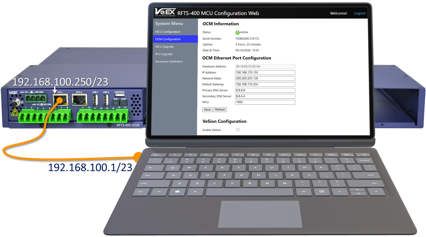
Connect a laptop or PC to the RFTS-400 OCM Eth-1 port.
-
Log In to the RFTS-400 MCU (Management Controller Unit).
Open a web browser and type in the IP address 192.168.100.250 in the address bar. Then, on the login screen enter your username and password, and select Login. If needed, find the default login credentials on the sticker located on the back of the OCM module. -
Modify the default RFTS-400 OCM IP Configuration and adjust the OCM Eth-2 network settings.
In the OCM Configuration section, customize the IPv4 Address, Netmask, Default Gateway, and DNS servers to align with your network setup. If the RFTS-400 OCM is connected via VPN or cellular network, set a smaller MTU value.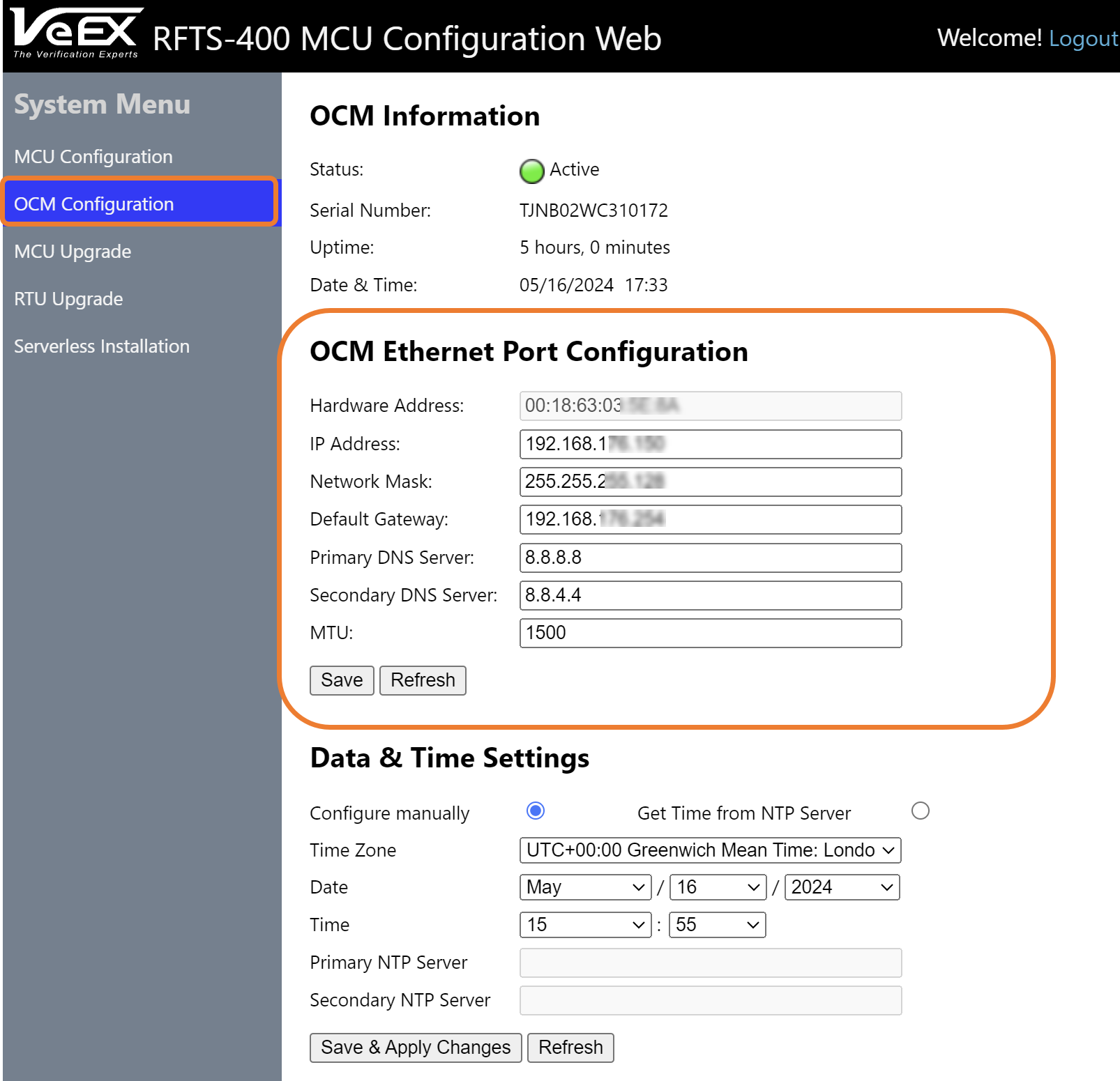
-
Click Save & Apply Changes.
![]() Access the OCM web interface by entering the updated IP address in a web browser. The default login credentials can be found on the sticker located on the top cover of the OCM.
Access the OCM web interface by entering the updated IP address in a web browser. The default login credentials can be found on the sticker located on the top cover of the OCM.
Follow these steps to reset the MCU to Factory default settings:
-
Power the OCM OFF.
-
Press and hold the Reset button (located on the back of the OCM), and the OCM Power button simultaneously until ETH-1 LEDs blink. This procedure will reset the MCU's IP settings, Username and Password to Factory default settings.
![]() This procedure will not affect any data or settings on the RFTS-400 OCM.
This procedure will not affect any data or settings on the RFTS-400 OCM.
|
|
If using VeSion to control the RFTS-400, the date and time information pulls from the VeSion server automatically. |
Synchronize every RFTS-400 unit operating in standalone mode to the UTC time standard. System administrators can configure up to two private or public NTP servers to ensure that the time and date remain accurate and up to date. Click here for a list of local, regional and global public NTP servers.
To configure NTP synchronization using the MCU interface
-
In the left panel, select OCM Configuration.
-
Under Date & Time Settings, select the Get Time from NTP Server option.
-
Enter the Primary and Secondary NTP server details, then click Save & Apply Changes.
To configure NTP synchronization using the Serverless Operation software interface
-
On the left menu, select RFTS setup
 , then for the Platform OCM, click
  .
. -
On the top menu, select System Settings
 .
. -
In the Date & time settings box, select the device time zone.
-
Enter the Primary and Secondary NTP server details, then click Apply.
To adjust the language and date/time format
-
In RFTS-400 Serverless Operation mode, select the user ID in the top right corner of the screen.
-
Select Settings in the dropdown menu.
-
Select the desired Language and Date/time format from the dropdown list of options.
Adding OSMs (Optical Switch Modules)
RFTS-400 OCM monitoring can be expanded with up to 16 RFTS-400 OSM modules (using three modular rack trays). The Control interface on the RFTS-400 OCM front panel is dedicated for communication with the optional RFTS-400 OSMs. Multiple RFTS-400 OSM modules can be connect to another RFTS-400 OSM, in a daisy-chain fashion, allowing a single RFTS-400 OCM to manage up to 16 RFTS-400 OSM switches.
|
|
RFTS-400 OSM modules cannot be connected or disconnected while the system is running. It is essential to power off the RFTS-400 OCM before adding a new RFTS-400 OSM module. |
|
|
Each RFTS-400 Optical Switch Module requires a unique switch ID, which can be configured using the DIP switches located on the back of the module. Please use the RFTS-400 Switch management software feature to help set the correct switch ID. |
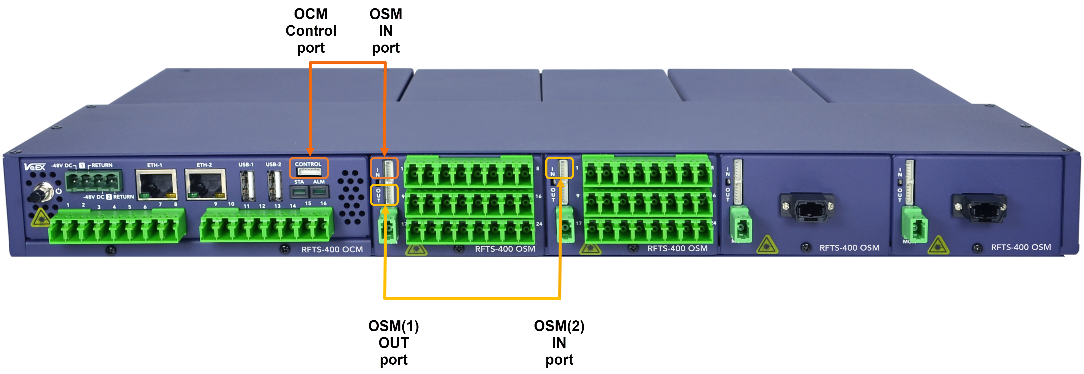
Use the control cable, included with each RFTS-400 switch, to connect multiple OSMs in series. When connecting the first switch module to the RFTS-400 OCM, use the control cable to make a connection between the OCM Control port on the and the IN port on the first OSM.
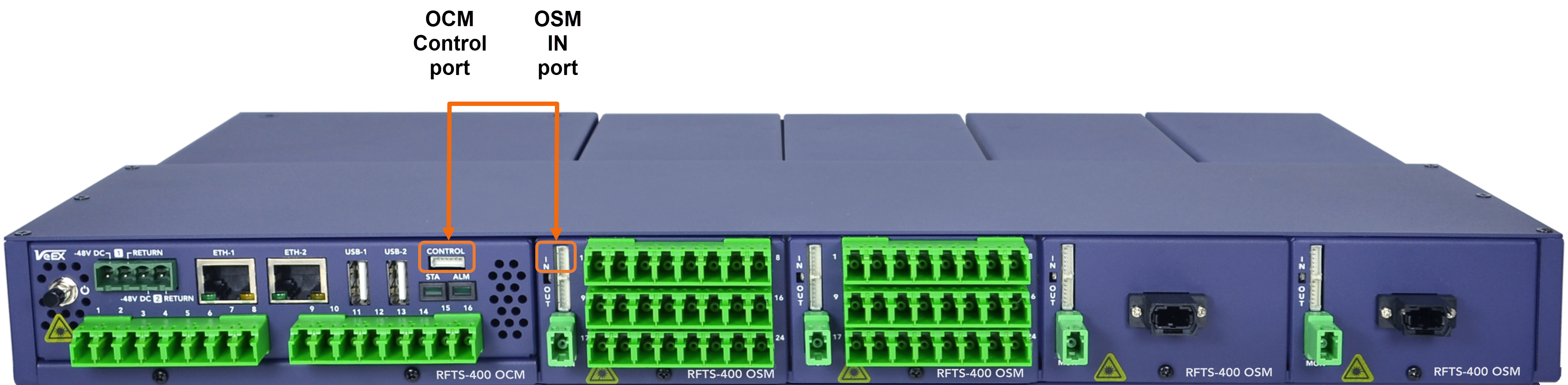
Every additional RFTS-400 OSM module is daisy-chained to the previous switch module, by connecting the OUT port to the IN of the next OSM.
Follow the DIP switch configuration for proper addressing of each of the optical test access units (OTAU) in the system, such as OSMs. Information about the individual DIP switch settings for each OSM can be found at RFTS Setup ![]() > RFTS Platform>OTAU Management.
> RFTS Platform>OTAU Management.
-
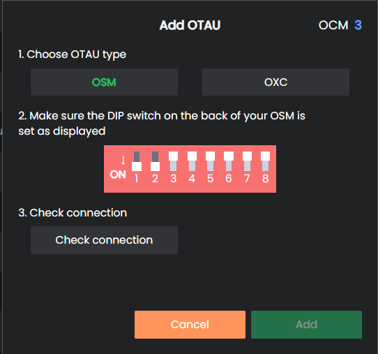
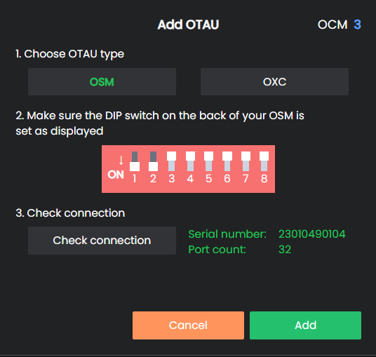
Select the OCM port that will be connected to the MON port of the OSM and click Add OTAU. The identification number for the OSM is determined by the port number of the OCM.
-
On the Add OTAU screen, choose the OSM switch type and click Add.
-
Ensure that the Optical Switch Module (OSM) has the matching switch ID as displayed in the User Interface (UI).
-
Click Check connection to confirm the communication status between the Optical Switch Module (OSM) and the Optical Control Module (OCM). Ensure that the system reads the OSM port count and the serial number by verifying that both values match the newly added OSM module.
-
Select the Add button to create and store the new optical switch cascade configuration.
![]() The OSM module ID is a logical address used by the OCM for signaling exchanges between the OCM and any particular OSM. This ID is independent of the physical OSM position or control wiring sequence (daisy-chain order).
The OSM module ID is a logical address used by the OCM for signaling exchanges between the OCM and any particular OSM. This ID is independent of the physical OSM position or control wiring sequence (daisy-chain order).
Configure SMTP (Email/SMS) and SNMP Notifications in Serverless Software Interface
The System Administrator can configure the following to send system and alarm notifications via email and/or text.
-
SMTP: Configure the SMTP to email notifications and the SMTP to SMS gateway, typically provided by a mobile operator or a third-party company, to send SMS Alarm notifications as a paid service.
-
SNMP Traps: Configure the SMNP to send SNMP traps to send alarm notifications to a northbound monitoring system.
To configure notifications, go to ![]() RFTS Setup >
RFTS Setup >![]() RFTS Platform >
RFTS Platform > ![]() Notification Settings.
Notification Settings.
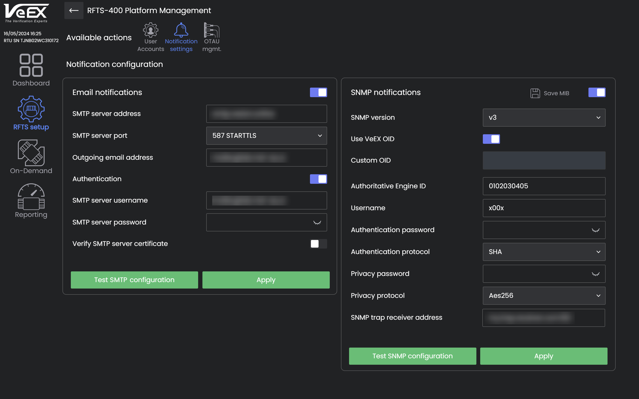
RFTS-400 Notification Configuration
Check your SMTP Server configuration before configuring email and SMS notifications.
|
|
Certain Internet Service Providers (ISPs) may restrict SMTP traffic outside their network as a measure to combat spam. Verify with your ISP any limitations concerning SMTP traffic within their network. |
SMTP configuration can vary depending on the setup. A basic configuration only requires the SMTP server address, server port, and a valid outgoing email address. A more typical configuration includes the server address, port, outgoing email address, and SMTP username and password if SMTP authentication is enabled. If the SMTP server uses an enterprise certificate for secure communication with the RFTS-400, the certificate verification may need to be disabled.
The system can transmit SNMP traps using SNMP V1 or V3 protocols to a northbound NMS (Network Management System). These traps are identified by the Enterprise Object Identifier (OID) 1.3.6.1.4.1.36290 as assigned by the Internet Assigned Numbers Authority (IANA). System administrators have the option to customize the OID if necessary.
-
SNMP V1 Traps: A valid SNMP Community name is needed (default is public), along with the SNMP trap receiver address and UDP port.
-
SNMP V3 Traps: The system follows the SNMP V3 User Security Model (USM) as outlined in RFC3414.
![]() Some SNMP trap receivers may not fully support all the security features mandated by the standard. Therefore, it is recommended to discuss the trap settings with the SNMP Trap receiver administrator for proper configuration.
Some SNMP trap receivers may not fully support all the security features mandated by the standard. Therefore, it is recommended to discuss the trap settings with the SNMP Trap receiver administrator for proper configuration.
Setup Users in Serverless Software Interface
The RFTS-400 Serverless software limits the number of concurrent user sessions to five. The system is designed to maintain system security by implementing four user roles.
![]() A good security practice is to avoid giving the default administrator account to multiple users. Instead, make a separate user account for each user that has to use the system. Use Port Groups so users will see only those ports they work on.
A good security practice is to avoid giving the default administrator account to multiple users. Instead, make a separate user account for each user that has to use the system. Use Port Groups so users will see only those ports they work on.
|
Notification Receiver |
Viewer |
User |
Administrator |
|
| Receive monitoring alarms | ☑ | ☑ | ☑ | ☑ |
| View monitoring results | ☑ | ☑ | ☑ | |
| Run On-Demand tests | ☑ | ☑ | ||
| Modify settings and thresholds related to fiber monitoring | ☑ | ☑ | ||
| Receive system notifications | ☑ | |||
| Modify system settings | ☑ | |||
| Create/modify/delete users | ☑ | |||
| GIS Management | ☑ |
Connect RFTS-400 (OCM) to VeSion Management and Monitoring System
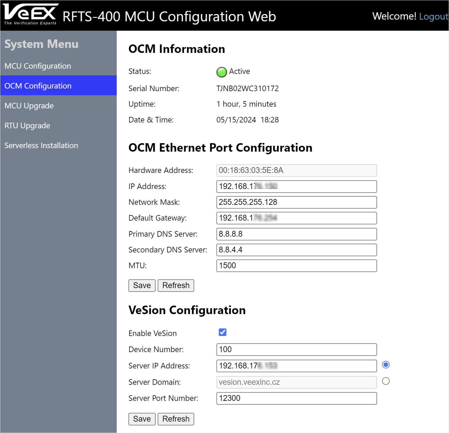
RFTS-400: VeSion Configuration
To connect to VeSion using the MCU interface:
-
In the RFTS-400 MCU Configuration web interface, select OCM Configuration in the left panel.
-
Check the Enable VeSion checkbox, then enter the information below, as needed and click Save.
-
Device Number: typically assigned by a VeSion RFTS Administrator for identification purposes
-
Server IP Address: IPv4 or IPv6 address
-
Server Domain: Fully Qualified Domain Name (FQDN) of the VeSion server
-
Server Port Number: VeSion server port number