Service Attributes
Bandwidth Profile Parameters
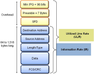
The Bandwidth Profile specifies how much traffic the customer is authorized to transmit and how the frames are prioritized within the network. In the Bandwidth table, the user specifies the following bandwidth criteria:
- CIR: Committed Information Rate. This is the guaranteed maximum rate at which the customer can send frames that are assured to be forwarded through the network without being dropped. Tap on the box to enter a rate and choose between IR Mbps or ULR Mbps. Allowed values range from 0.01Mbps to the line bandwidth.
- Information Rate (IR): Measures the average Ethernet frame rate starting at the MAC address field and ending at the CRC.
- Utilized Line Rate (ULR): Measures the average Ethernet frame rate starting with the overhead and ending at the CRC.
V-SAM Services - Header
- Excess Information Rate (EIR): Maximum rate above the CIR at which the customer can send frames that will be forwarded on a best effort basis, but may be dropped in the event of congestion within the network. The combined CIR and EIR must not exceed the line bandwidth. Traffic beyond CIR + EIR will be dropped when it enters the carrier's network. Tap on the box to enter a rate. EIR is expressed in terms IR Mbps or ULR Mbps. Select a term to express EIR or select Disable to disable the test.
- Traf. Policing: Enable or Disable the traffic policing test. For this test, traffic is transmitted at 25% higher than the CIR+EIR. The Policing test fails if the higher traffic rate is allowed through the network.
- Color Aware: Enable, Disable. When Color Aware is enabled, the Drop Eligible parameter in the VLAN header configuration screen is not available for configuration. If no VLAN is configured for the service traffic, the Color Aware parameter is ignored.
- CBS and EBS: Committed Burst Size (CBS) and Excess Burst Size (EBS).
- CBS can be enabled without enabling EBS
- If EBS is enabled, then CBS is automatically enabled too
- Values between 4 KBytes and 100 KBytes can be input for both CBS and EBS
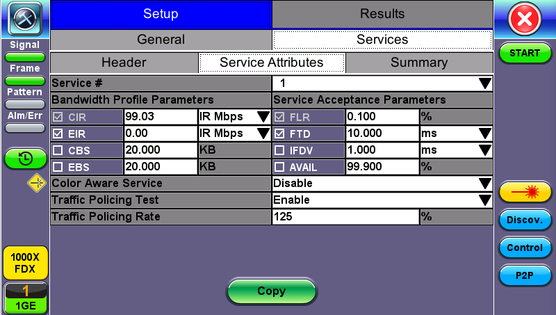
V-SAM Setup - Services - Service Attributes
![]() Enabling/Disabling Tests
Enabling/Disabling Tests
A check next to the parameters in the Service Attributes table indicates that the test for the corresponding service is set to run. Tap on the box to remove the check and cancel the test for that service.
Service Acceptance Parameters
The user establishes Pass/Fail test criteria for the following Service Acceptance Criteria. Values define the minimum requirements to ensure that the service meets the Service Level Agreement (SLA):
-
FLR: Maximum ratio of lost frames to the total transmitted frames allowed to still be compliant with the SLA. FLR is only guaranteed for traffic conforming to the CIR. Enter a percentage from 0-100.
-
FTD: Maximum transfer time that the frames can take to travel from source to destination, and still be compliant with the SLA. FTD is only guaranteed for traffic conforming to the CIR. Values are measured in us, ms, or sec. Input a value within the digital range of .001-999 and 1 us-999sec. The user can also choose to Disable the FTD threshold evaluation. FTD will be measured anyway but the value will not contribute toward passing or failing the service.
-
IFDV: Maximum frame jitter allowed to still be compliant with the SLA. FDV is only guaranteed for traffic conforming to the CIR. Values are measured in us, ms, or sec. Input a value within the digital range of .001-999 and 1 us-999sec. The user can also choose to Disable the IFDV threshold evaluation. IFDV will be measured anyway but the value will not contribute toward passing or failing the service.
-
AVAIL: Minimum percentage of service availability allowed to still be compliant with the SLA. The service becomes unavailable if more than 50% of the frames are errored or missing in a one second interval. Availability is only guaranteed for traffic conforming to the CIR. Enter a percentage from 0-100. The user can also choose to Disable the AVAIL threshold evaluation. AVAIL will be measured anyway but the value will not contribute toward passing or failing the service.
Copying Services
![]() Copying Services
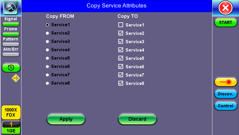
Copying Services
Tap on the Copy button on the bottom of the Header or Service Attributes tabs to copy frame parameters specific to that tab to other services. For example, pressing Copy on the Header tab will only transfer header parameters to other services.
MX Discover and Control Settings
The Control button offers additional loopback control settings including User Defined and OAM Discover.
For instructions on how to loop up/down the test set with another test set or device, please refer to MX Discover and Control Settings.
Peer-to-Peer Setup
Peer-to-Peer and asymmetric testing via the P2P Setup button is also available.
Remote Partner Control
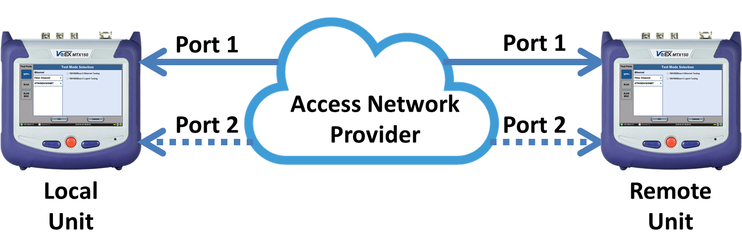
When the local unit connects to the remote (peer) partner, it loads the same configuration profile (header, traffic, and frame size) to the remote partner, with the MAC and IP addresses inverted. From the peer-to-peer menu, asymmetric testing becomes available.
Asymmetrical links provide different line rates in the two directions. To verify the information for both the low and the high rates of the link, the user needs to send a test signal from one instrument located at one end of the link to an instrument at the other end of the link and vice versa to test traffic capacity. The two test instruments have to be synchronized because the tests defined in RFC 2544 require the receiver to know the contents of the test signal to be transmitted in detail.
The test set offers an automated RFC 2544 test application to perform throughput, frame loss, and burstability tests in a local-remote unit setup. The user first configures the test setup in the local unit. Once initiated, the local unit transfers the setup information to the remote unit via the line under test. Upon completion, the remote unit transfers the test results back to the local unit, enabling the user to read the results for both directions of the link on the local unit.
Asymmetric Testing Setup
- Tap the P2P Setup button on the right side of the screen to start the step-by-step setup process.
- Set the Local unit as a Controller or Responder.
At any time during the process, tap on the right side navigation buttons to move to the NEXT screen, return to the Previous screen, or Exit the setup guide.
Set the Local unit as Controller or Responder
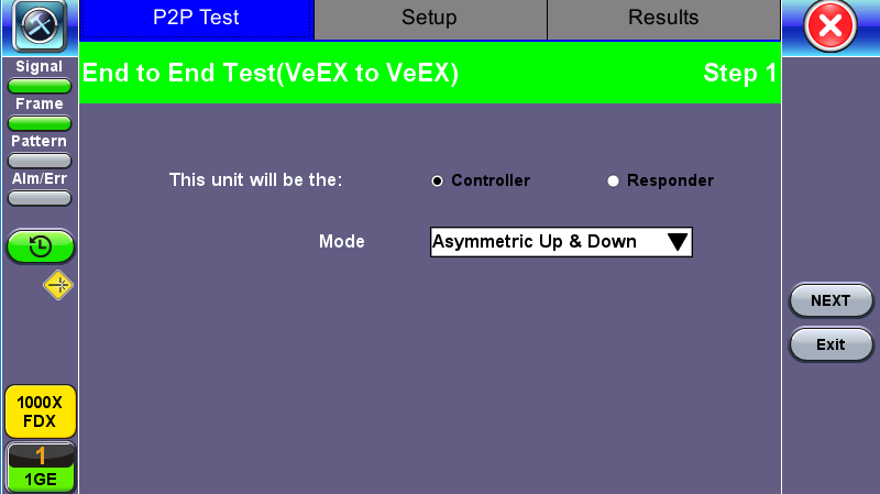
Unit as Controller Setup Process
- Step 1: Select Controller.
- Mode: Select an asymmetric test configuration.
- Asymmetric Up: Tests traffic in the upstream direction (local to remote direction).
- Asymmetric Down: Tests traffic the downstream direction (remote to local direction).
- Asymmetric Up & Down: Test traffic in both upstream and downstream direction.
- Mode: Select an asymmetric test configuration.
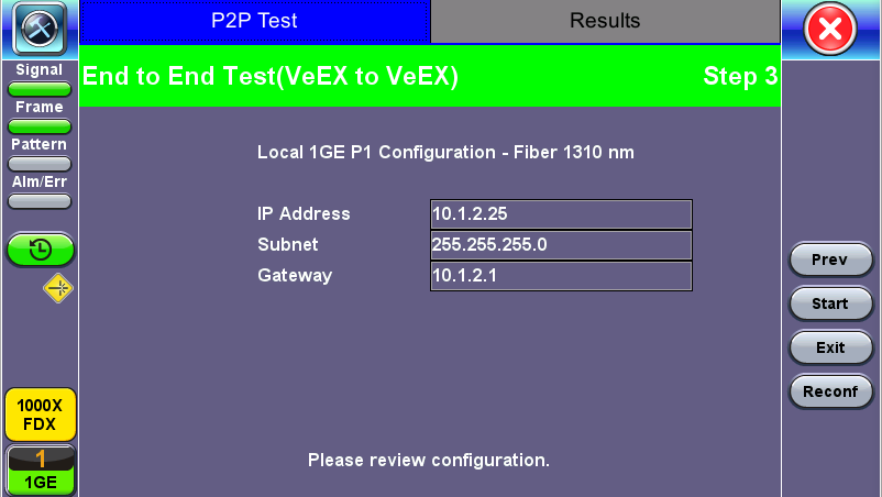
- Step 2-7: Make the following selections for the Controller and Remote units: Layer, IP Address, Subnet, Gateway, and VLAN tags. Tap on the white fields to edit options. Use the alphanumeric keyboard to input parameters and press Apply to save edits.
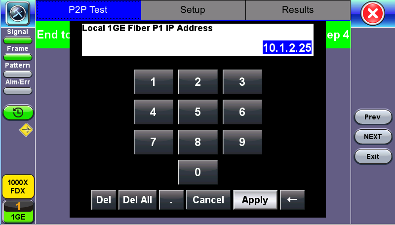
Input screen
- Step 8: Tap on the check boxes to add local frames. Tap on the Add Frame button to add a customized frame size.
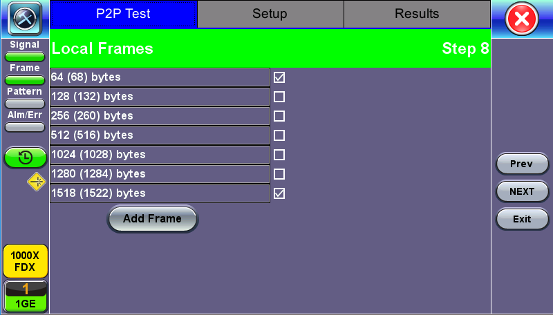
Controller - Step 8
- Steps 9-12: Set up and enable/disable tests for the Local unit.
- Step 9: Local Throughput testing setup. See the Throughput section for a description of menu options.
- Step 10: Local Frame Loss testing setup. See the Frame Loss section for a description of menu options.
- Step 11: Local Burst testing setup. See the Burst (Back-to-Back) section for a description of menu options.
- Step 12: Local RX Thresholds setup. See the Thresholds section for a description of menu options.
- Steps 13-16: Set up and enable/disable tests for the Remote unit. See Steps 8-11 for information on setting up individual tests.
- Step 17: Review configuration selections on the summary screen. The option to Start testing or Reconfigure test settings becomes available.
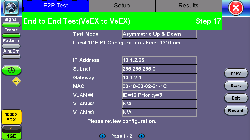
Controller Summary Screen
Unit as Responder Setup Process
- Step 0-2: Tap on the white fields to setup the Local unit's IP Address, Subnet, and Gateway. Tap on Next to setup VLAN tags using the drop-down menu.
- Step 3: Review configuration selections. The option to Start testing or Reconfigure test settings becomes available.
Responder Summary Screen
RFC 2544 Local and Remote Test Setup
RFC 2544 Test setup for the local and remote unit is available in the Setup tab. Refer to Setup - Standard Mode for more information.
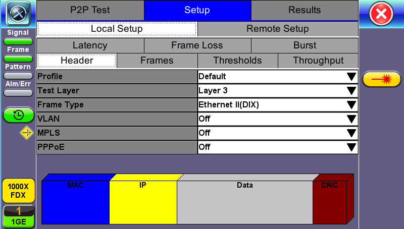
Local Setup
Test Results
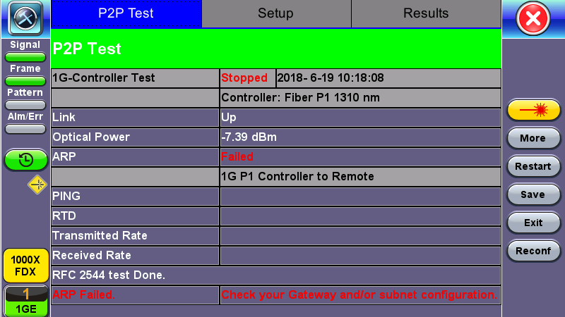
P2P Test Results
Packet Capture
To capture packets, tap PCAP. Tapping PCAP again will stop packet capture and automatically name and save results in pcap format. A message displays the name of the saved file located in Files > Saved section of the test set. The file and can be exported to a PC and analyzed using Wireshark.
See File Manager for information on viewing saved files.