Baseline Modeling
Use Baseline Modeling to reflect a more accurate picture of the fiber route with components such as cable segments, manholes, and handholes. This results in a more precise analysis of measurements. On the Baseline Modeling screen:
-
Add, edit, or delete events.
-
Mark fiber segments.
-
Label events to match network.
To turn turn on/off the GIS map at the top of the screen, select ![]() in the top right corner.
in the top right corner.
![]() Add demarcation points to minimize the inaccuracies caused by the Optical to Geographical distance conversion. The system will report distances to the two nearest demarcation points automatically. Precise fiber section settings will be helpful when analyzing reporting to discover issues before they become server. Refer to Fiber Segment Attenuation Report.
Add demarcation points to minimize the inaccuracies caused by the Optical to Geographical distance conversion. The system will report distances to the two nearest demarcation points automatically. Precise fiber section settings will be helpful when analyzing reporting to discover issues before they become server. Refer to Fiber Segment Attenuation Report.
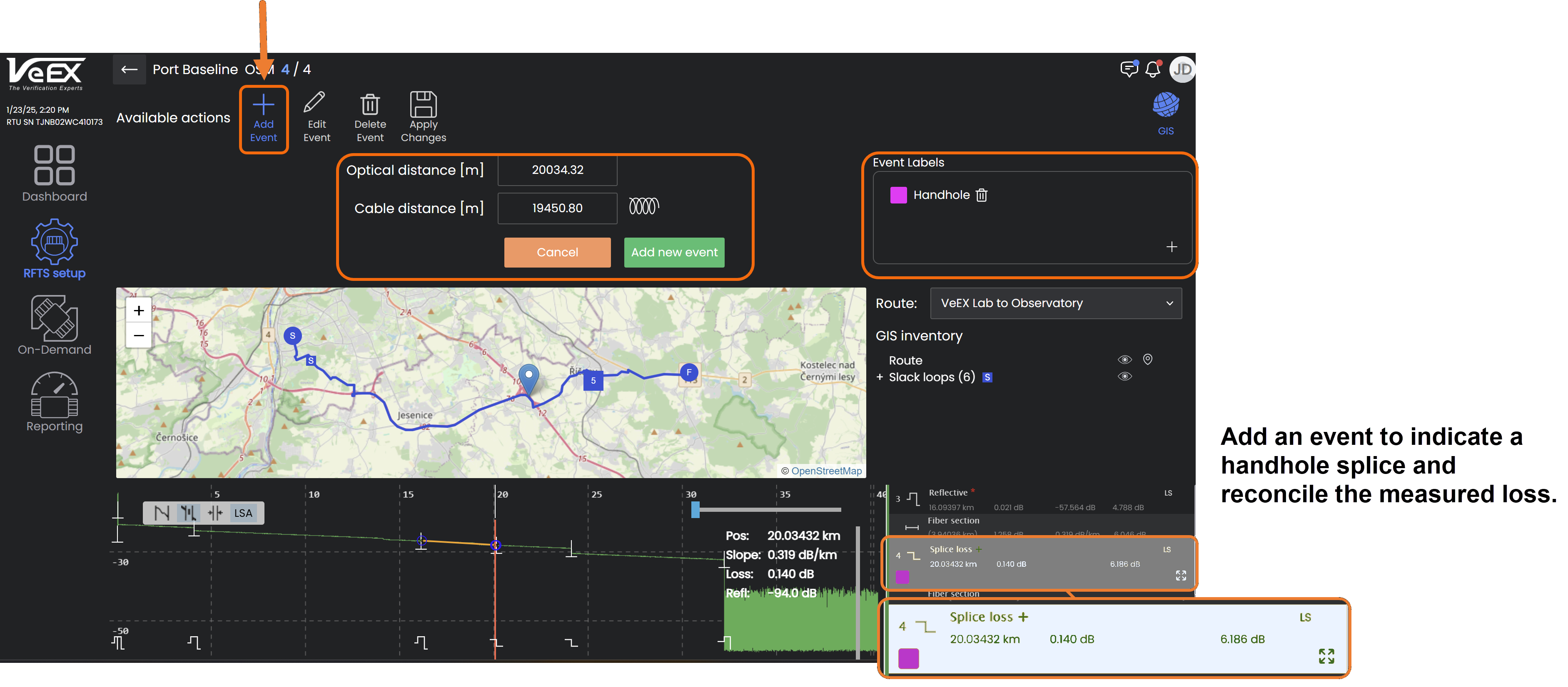
Add/Edit/Delete Events
Add events attributed to network components e.g. manholes.
-
In the event table, select and highlight the fiber segment where the event is located.
-
Select Add event or Edit event.
-
Enter the cable distance.
-
If needed, select
 to enter the Helix Factor. The optical distance will change accordingly.
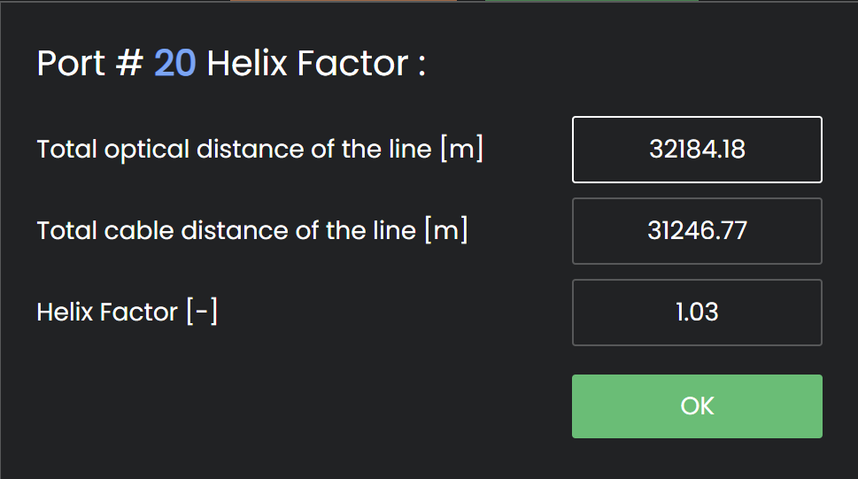
-
Select Add new event or Apply changes.
-
Select
 after adding, editing, or deleting an event.
To remove an event, select and highlight the event in the event table and select Delete event.
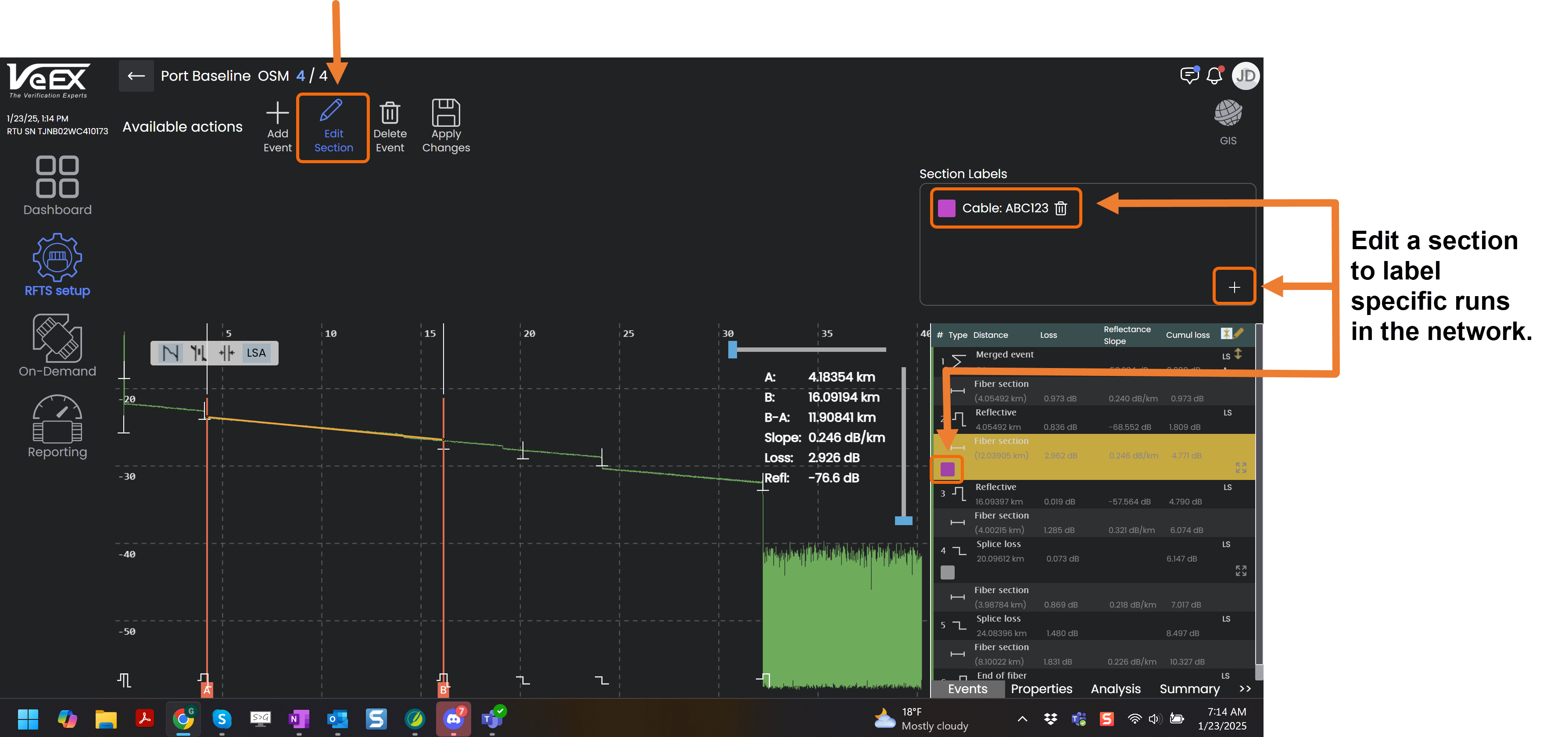
Label Segments/Events
Label network components for easy identification when analyzing traces.
-
In the event table, select and highlight the segment or to label.
-
Select Edit Section or Edit Event.
-
In the Section Label box, select the plus sign
 and enter a name for the label.
 -
Select
 to choose a unique color for the label.
 -
Select
 to assign the label to the component. Select
  to discard the label before assigning it.
 -
Select
to save the label.
To remove a label, select and highlight the event in the event table, then select ![]() .
.