OPM Test Modes
Inspect and clean the test ports. Inspect and clean the fiber patch cord from the OLT and insert it into the test set OLT test port.
|
|
Connection Process
Connect the test set at the customer premises between the ONT/ONU and the last splitter in the ODN. Do NOT connect the test set between the OLT and splitter without attenuation.
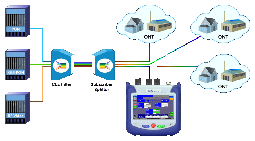
The FX120 should be connected between the splitter and ONT.
The test set will synchronize to the downstream frame (from the OLT) provided the OLT is operational and 1490/1577nm signal level is good. The downstream frame synchronization indicator should occur almost immediately.
To synchronize with the ONU, the test set needs to see the ONU registration process. Therefore, only connect the ONU AFTER the PON OPM application is already running. Otherwise, unplug and replug the ONU after the PON OPM application is running if the ONU is already connected to the test set.
![]() If the OLT and an active ONU are connected to the test set before starting the test application, the test set will not see the ONU activation and the above process will not be completed. In this instance, LOF will be reported for the upstream side; no ONU ID or ONU S/N information on the OPM results page will be displayed.
If the OLT and an active ONU are connected to the test set before starting the test application, the test set will not see the ONU activation and the above process will not be completed. In this instance, LOF will be reported for the upstream side; no ONU ID or ONU S/N information on the OPM results page will be displayed.
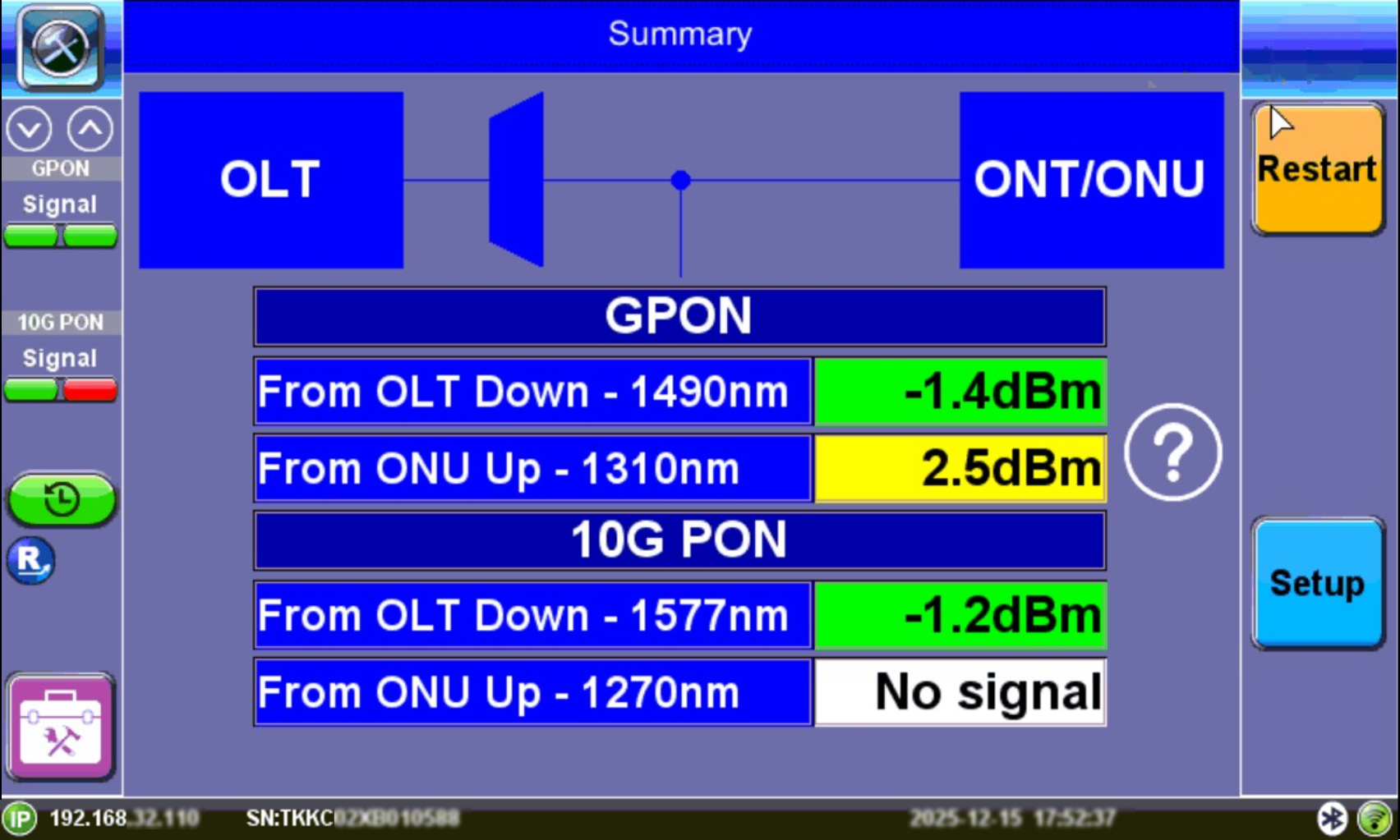
A selective (filtered) optical power meter (OPM) separates coexistent G-PON/EPON 1490 nm and XGS-PON/10G EPON 1577 nm downstream wavelengths, to simultaneously measure their individual optical power levels. These measured signal levels can be compared against standard (or customized) minimum and maximum thresholds expected for different network points to diagnose if the physical link passes or fails the applicable installation requirements. Verify the ONU-ID and Serial Number and ONT status upon completion of ONU activation. If laser instability is suspected, monitor the signal/ODN loss budget graph to verify signal stability over time. Refer to Histogram and ODN Loss History.
The PON-T refers to a PON Terminating device or instrument, such as the FX120T, that is used at the end of the fiber link (or segment) under test (opposed to pass-through or monitoring devices). For example, a PON-T Optical Power Meter is a selective or filtered OPM that is to be connected at the end of the fiber under test.
Test Procedure
-
Power on the test set. Testing should start automatically. Restarting measurements from the OPM menu (see OLT and ONT/ONU Messages) resets items in the OPM Summary screen (power level graphs and Active ONU list). To clear the PLOAM list, go to the respective PLOAM menu and press the Clear button.
-
Select Setup and configure the test profile settings according to the xPON class and ITU-T Test standards for GPON/XGS-PON or EPON IEEE Test standards for EPON/10G EPON. Refer to OPM Setup.
-
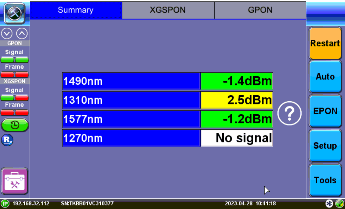
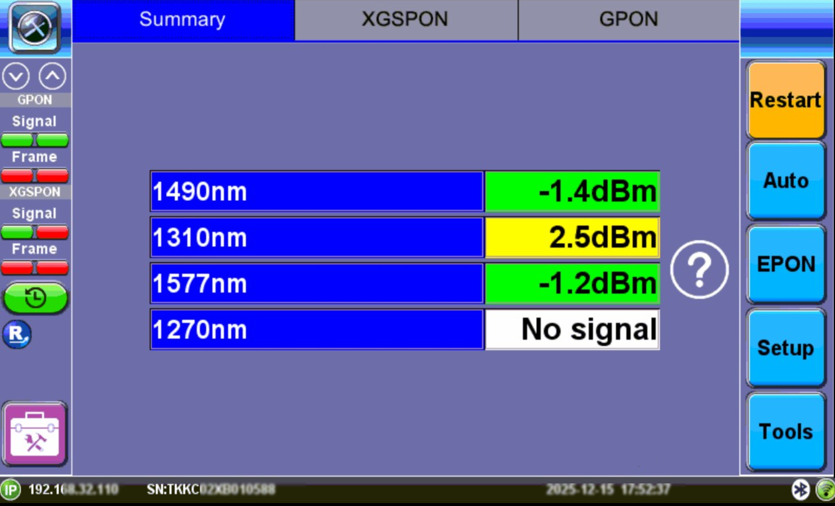
Inpect and clean the test ports and fiber patch cord from the OLT, then insert it into the OLT test port. If 1490/1577nm light is detected, the 1490/1577nm Status will display OK. Verify that the measured 1490/1577nm signal level is green.
Warning: Never look directly into the beam of an active optical source as this may result in harmful eye damage from radiation exposure.
-
All DS LEDs should turn from red to Green. If any LED remains red, clean and inspect the connectors again as specified in Step 3.
-
Inspect and clean the patch cord connectors that will connect the test set to the ONU/ONT, then connect the test set to the ONU/ONT test port. If 1310/1270nm light is detected, the Status will display OK. Verify that the measured 1310/1270nm signal level is green.
-
All US LEDs should turn from red to green. If any LED remains red, clean the ONU connections again as outlined in Step 5.
-
Confirm TC-Sync status displays OK DL. If you are not able to achieve TC-Sync, contact VeEX Inc. Support. Refer to Upstream/Downstream/TC-Sync Signal Status.
Pass-Through Views
In the OPM Summary view, LEDs indicate if upstream/downstream signals are present and frame quality.
To simplify the view and see the OPM readings only on the main screen, select Setup, then select On for OPM Only. Refer to OPM Setup.
Summary View
OPM Only View
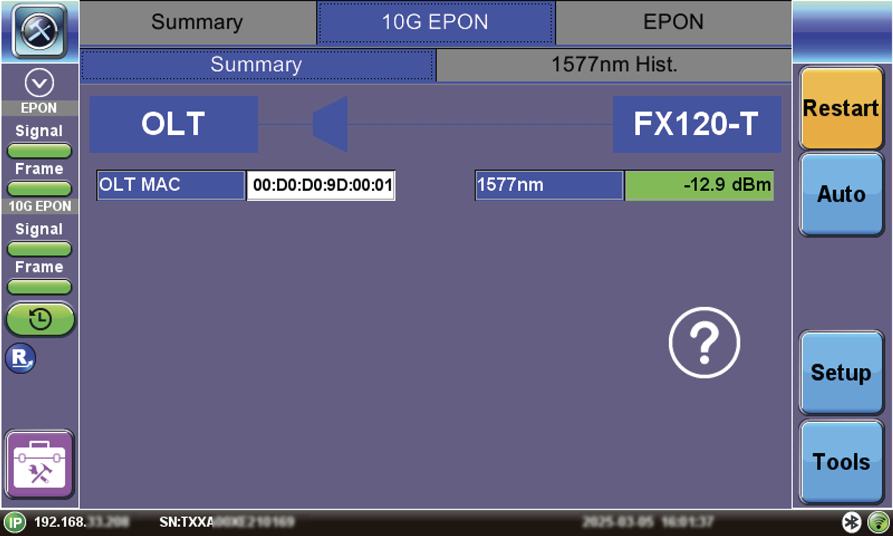
FX120T View
Green, yellow, and red table colors indicate whether signal levels pass or fail against ITU-T/IEEE standard threshold values configured in Setup.
Refer to OPM Setup for information on test profile setup.
 Green: The measured signal is above the marginal threshold.
 Yellow: The measured signal is below marginal and above critical.
 Red: The measured signal level is below the critical threshold and does not meet the specification.
LEDs indicate if upstream/downstream signals are present and frame quality. Signal levels and ODN Loss will indicate Pass/Fail per ITU-T or user defined limits. If laser instability is suspected, monitor signal/ODN loss budget history to verify signal stability over time.
Refer to OPM Power Measurement Results for a description of OPM Results.