OPM Power Measurement Results
Contrary to common Broadband OPMs, which don't discriminate between the optical signals coming in, a Selective PON OPM WILL NOT measure signals outside of its working bands (e.g., 1490 nm for 1G, 1577 nm for 10G) and it will display Low or very attenuated values for any other wavelengths that may be present in the fiber under test.
Certain optical distribution networks carry a TV Broadcast signal over the 1550 nm wavelength, however, that does not affect the accuracy of the GPON and XGS-PON level measurements, when the right selective OPM is being used.
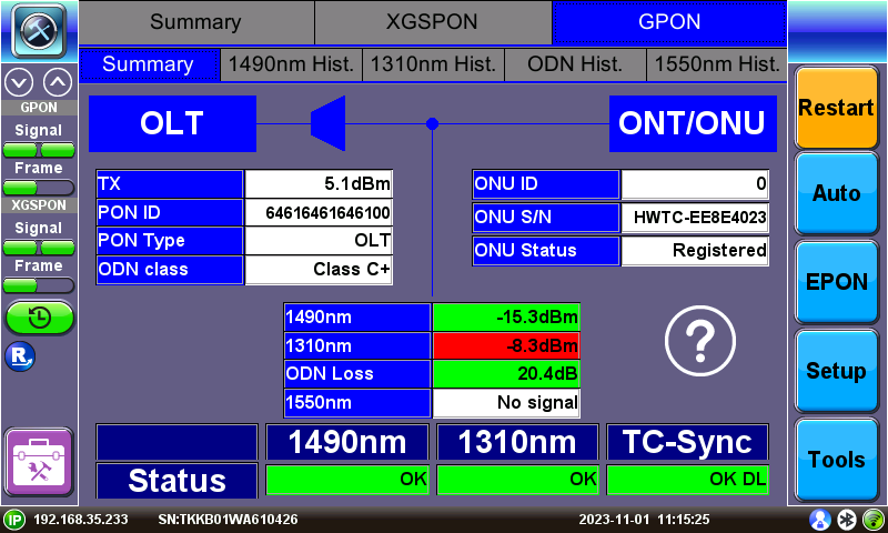
The GPON/XGSPON/EPON/10G EPON Summary screen shows the PON ID and optical power levels for these modes.
LEDs indicate if upstream/downstream signals are present and frame quality. Signal levels and ODN Loss will indicate Pass/Fail per ITU-T or user defined limits. If laser instability is suspected, monitor signal/ODN loss budget history to verify signal stability over time.
When Test Point Compensation is turned on, a TPC indicator ![]() is shown on the left and displayed measurements reflect the actual signal strength, even when attenuation is applied. Refer to Test Point Compensation (TPC) for Attenuation Adjustment.
is shown on the left and displayed measurements reflect the actual signal strength, even when attenuation is applied. Refer to Test Point Compensation (TPC) for Attenuation Adjustment.
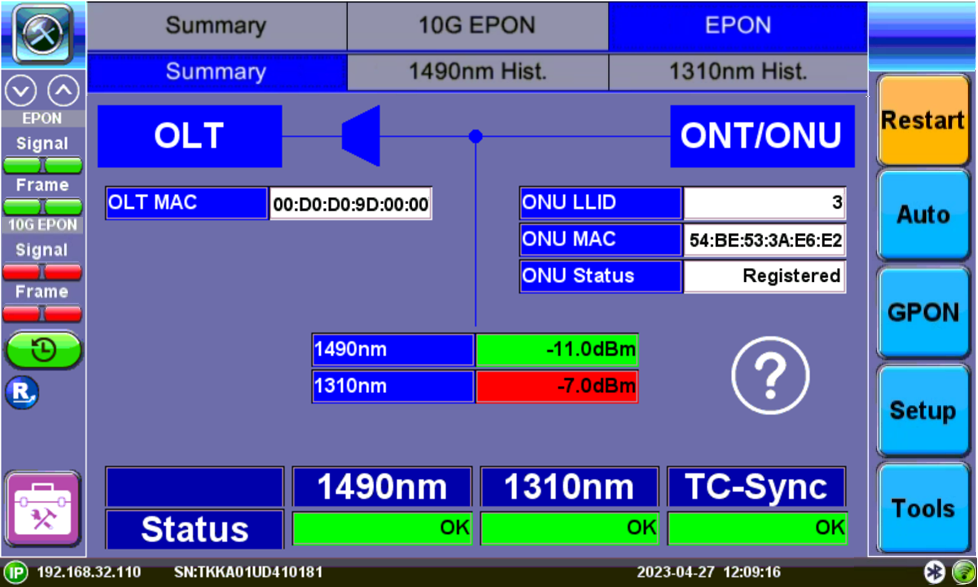
EPON Summary Screen
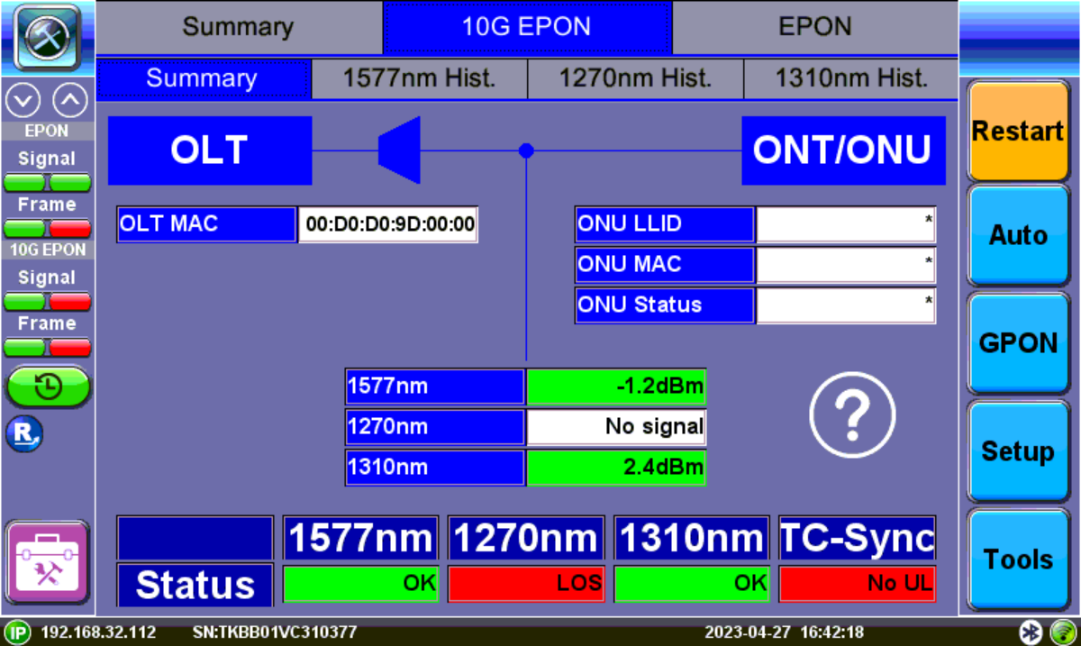
10G EPON Summary Screen
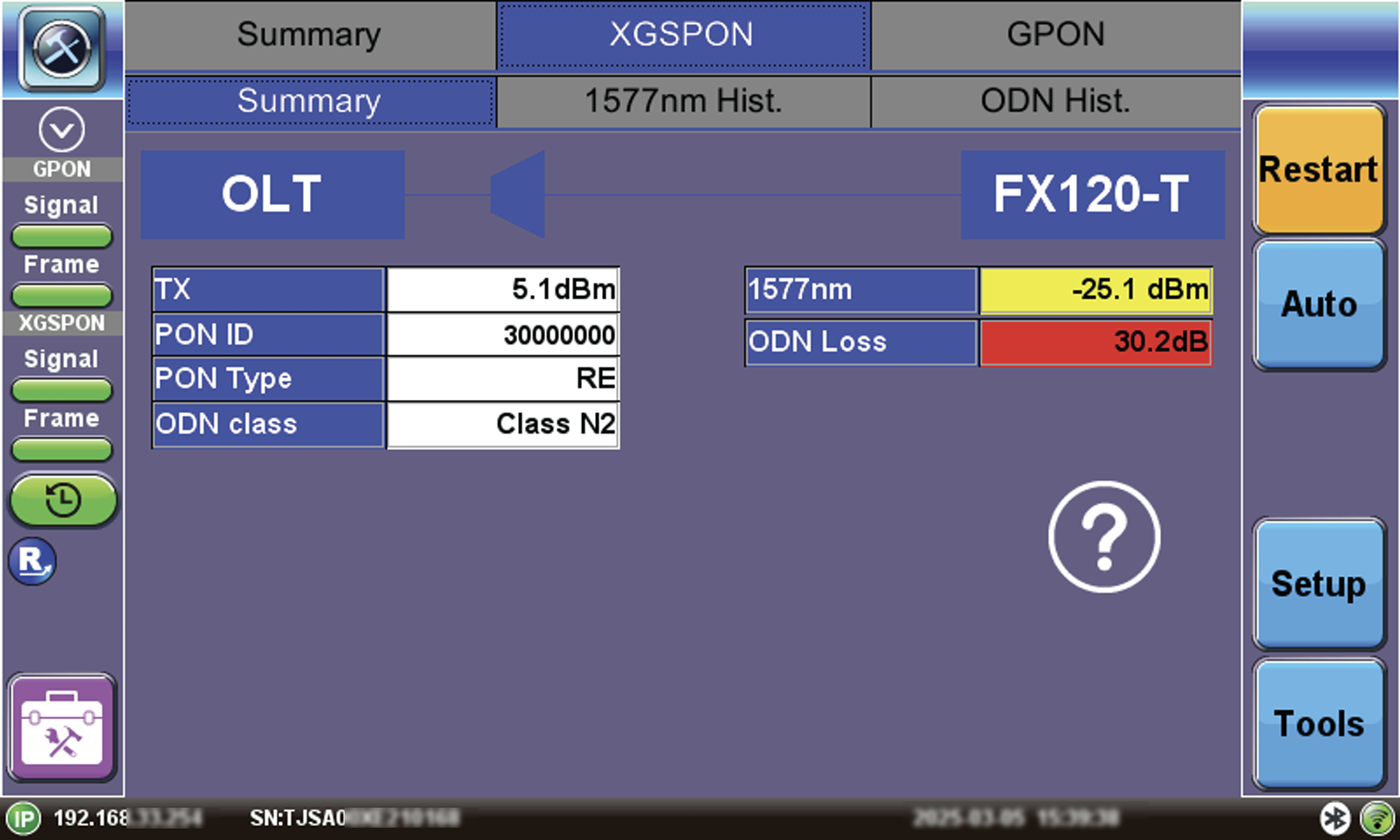
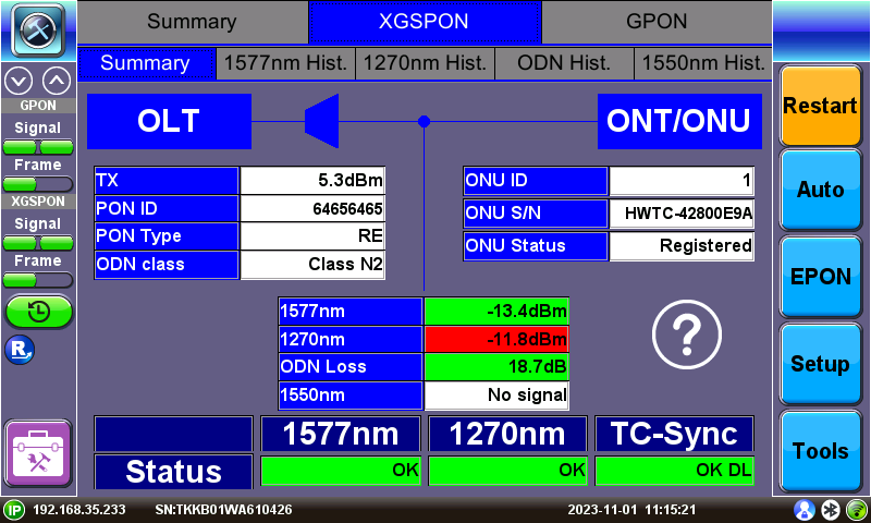
FX120-T XGS-PON Summary Screen
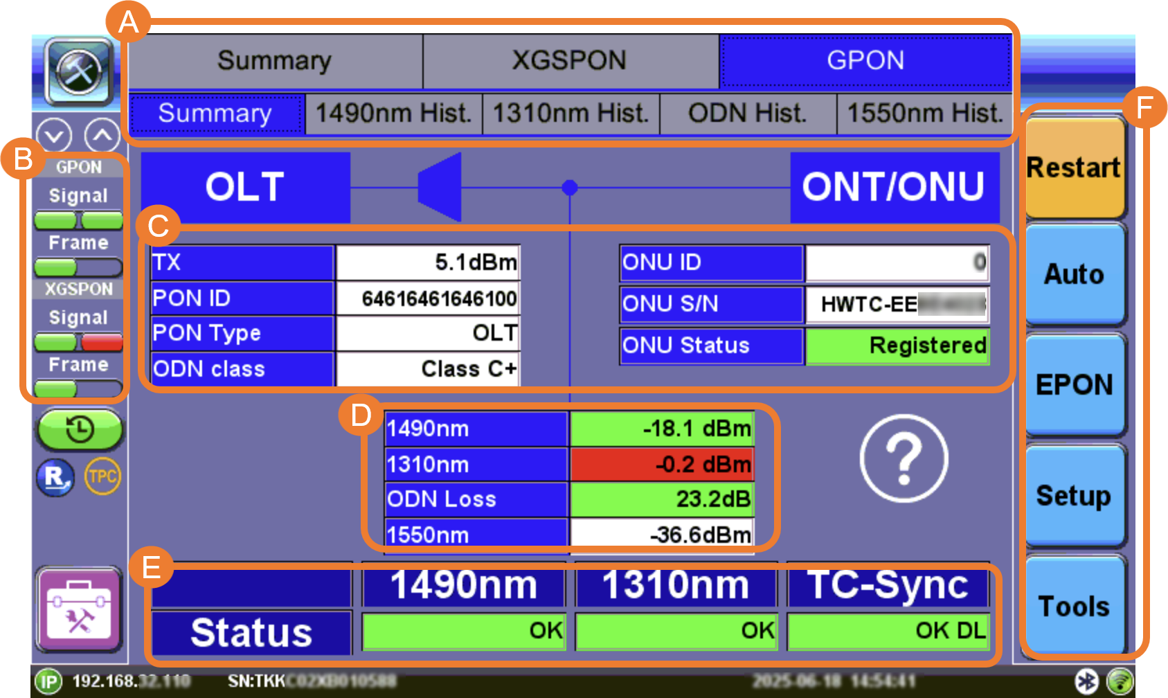
A. Power level measurement tabs to view the corresponding GPON/XGS-PON/EPON/10G EPON upstream and downstream signals, histograms.
B. LED signal status indicators
C. OLT and ONT/ONU Information
D. Signal measurements and ODN Loss
E. Pass/Fail Statuses
F. Function buttons
Restart: Restarts synchronization process.
Auto: Detects which network your fiber is connected to and automatically load the correct information on the screen.
EPON/GPON: Switches between EPON/10G EPON and GPON/XGS-PON modes.
Setup: Accesses setup and thresholds. Refer to OPM Setup.
Tools: Accesses advanced OPM functions, such as PLOAM messages, active ONUs, and OC field decoder.
GPON/EPON LED Status Indicators
On screen LED colors indicate the status of downstream (left) and upstream (right) signals and downstream frame detection.
![]()
GPON/XG(S)-PON Downstream/Upstream LED Status
![]()
EPON/10G EPON Downstream/Upstream LED Status
-
Green: Signal level detected. No errors or alarms are present. No further action required.
-
Red : An error condition is detected and is currently present. Flashing red indicates a history condition—an error was detected during the measurement interval but it is no longer present or active. Tap TOOLS to view PLOAM, and Active ONU.
The History button resets the LEDs of past statuses.
![]() If any LED remains red, clean the patch cord connectors that will connect the FX120/FX120 Lite to the ONU/ONT, the FX120/FX120 Lite test ports (To ONU, To OLT), and the ONU/ONT ports. Refer to Inspection for information on inspecting and cleaning fiber connectors.
If any LED remains red, clean the patch cord connectors that will connect the FX120/FX120 Lite to the ONU/ONT, the FX120/FX120 Lite test ports (To ONU, To OLT), and the ONU/ONT ports. Refer to Inspection for information on inspecting and cleaning fiber connectors.
OLT and ONT/ONU Messages
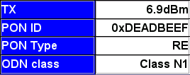
GPON/XGS-PON OLT Information Table

EPON OLT Information Table
Below the OLT and splitter diagram block, a table displays the transmitting signal level (TX), PON ID, PON Type, and ODN class. For EPON testing, the MAC number is displayed. This is decoded from downstream PLOAM messages from the OLT. This information is only available when sent by the OLT and may need to be enabled.
GPON/XGS-PON
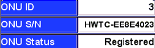
ONU Information Table
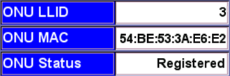
EPON/10G EPON
ONU Information Table
GPON/XGS-PON ONU ID, ONU S/N, and ONU status information and EPON ONU LLID, ONU MAC, and ONU status information is decoded from downstream PLOAM messages from the OLT that was received from the ONT/ONU during the initial service activation. If the information is not displayed, it may have been missed. Power cycle, or disconnect then reconnect, the ONU to initiate the ranging process again.
| ONU Status | Cause | Result |
|---|---|---|
| Activated | ONU/ONT registered with OLT. Communication established and in Sync. | PON network will operate properly. |
| Rogue | ONU/ONT = faculty ==> ROGUE ONT. ONU transmission detected outside Bwmap; CW Tx; BIP errors detected. | ONU Operations stopped. disable_SN or emergency_stop sent. |
| Unregistered | ONU/ONT not registered at OLT. Not in OLT list of registered ONU/ONTs. | ONU Operations stopped. Deactivated or eStop PLOAM sent. |
| Alien | Unknown device connected. | May lead to disruption on some or all services on shared PON-ID. |
Refer to ONU/ONT Statuses for more information.
Power Measurements
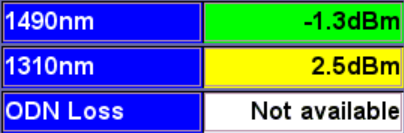
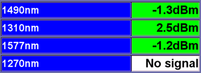
GPON Signal Measurement Table
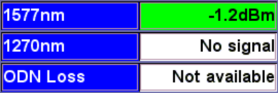
XGS-PON Signal Measurement Table
EPON Signal Measurement Table
At any customer location after the OLT and splitter, the test set will display 1490nm and 1310nm signal level values for GPON, 1577nm and 1270nm for XGS-PON, and 1550nm for RF/CATV. ODN Loss is the difference between the transmitting signal from the OLT (TX) and the DS signal level measured at the test set location.
![]() If the OLT is not broadcasting its transmit power, the span loss value cannot be calculated.
If the OLT is not broadcasting its transmit power, the span loss value cannot be calculated.
Green, yellow, and red table colors indicate whether signal levels pass or fail against ITU-T/IEEE standard threshold values configured in Setup.
Refer to OPM Setup for information on test profile setup.
 Green: The measured signal is above the marginal threshold.
 Yellow: The measured signal is below marginal and above critical.
 Red: The measured signal level is below the critical threshold and does not meet the specification.
Upstream/Downstream/TC-Sync Signal Status
Refer to Signal and Synchronization Status for information on TC-Sync statuses.
Test and Profile Settings
-
Setup: Setup Test profile
-
Advanced: Leads to the Advanced Setup, Results, PLOAM Decoder, and Active list.
Signal and Synchronization Status
The Status table displays detected 1490nm/1577nm downstream, 1310nm/1270nm upstream, and TC-Sync status.
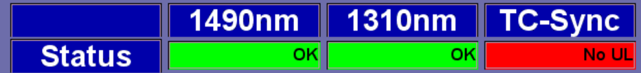
GPON Signal and Synchronization Status Table
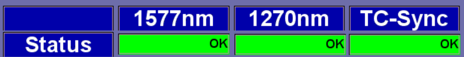
XGS-PON Signal and Synchronization Status Table
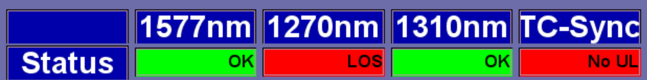
10G EPON Signal and Synchronization Status Table
Status Table
-
1490nm/1310nm: If OK is displayed, light in the downstream 1490nm or upstream 1310nm direction is detected.
-
1577nm/1270nm: If OK is displayed, light in the downstream 1577nm or upstream 1270nm direction is detected.
-
1577nm/1270nm/1310nm: If OK is displayed, light in the downstream 1577nm or upstream 1270nm direction or upstream 1310nm is detected.
-
Transmission Connectivity Sync (TC-Sync): OK DL indicates that the FX120 is properly synchronized with the OLT and ONU/ONT traffic based on downstream information. No DL indicates the OLT and ONU/ONT are not synchronized properly. Consult VeEX technical support if unable to achieve TC-Sync.
![]() OK indicates US or DS light is detected, but does not indicate whether ITU-T Threshold values (IEEE values for EPON) are met or if the OLT and ONU/ONT are properly synchronized.
OK indicates US or DS light is detected, but does not indicate whether ITU-T Threshold values (IEEE values for EPON) are met or if the OLT and ONU/ONT are properly synchronized.